Multifunction device

a multi-functional device and multi-function technology, applied in the field of multi-functional devices, can solve the problems of increasing the size difficult to recognize the image, and complicated shape of the multi-functional devi

Inactive Publication Date: 2010-11-02
BROTHER KOGYO KK
View PDF17 Cites 14 Cited by
  • Summary
  • Abstract
  • Description
  • Claims
  • Application Information

AI Technical Summary

Benefits of technology

[0008]Therefore, a need has arisen for multifunction devices which overcome these and other shortcomings of the related art. A technical advantage of the present invention is that the image readily may be recognized when a user of a multifunction device views the image on the display portion without increasing a size of the multifunction device. Another technical advantage is that a portion of the display portion which is not used to display the image may be minimized.
[0009]According to an embodiment of the present invention, a multifunction device comprises an image scanning unit and an image printing unit. The multifunction device further comprises operation panel which is positioned on a front side of the image scanning unit. The operation panel comprises a display portion. Each of the display portion and the operation panel has a horizontal center line and a vertical center line witch is perpendicular to the horizontal center line. A length of the vertical center line of the display portion is about equal to a length of the vertical center line of the operation panel. A ratio of a length of the horizontal center line of the display portion to the length of the vertical center line of the display portion is greater than 4 / 3.
[0010]According to another embodiment of the present invention, a multifunction device comprises an image printing unit. The image printing unit comprises a front wall, a back wall opposite the front wall of the image printing unit, and at least one side wall which is connected and substantially perpendicular to each of the front wall of the image printing unit and the back wall of the image printing unit. A distance between the front wall of the image printing unit and the back wall of the image printing unit comprises a maximum depth dimension of the multifunction device. The multifunction device further comprises an image scanning unit mounted to the image printing unit. The image scanning unit comprises a back wall, and at least one side wall which is connected to the back wall of the image scanning unit. The back wall of the image scanning unit is continuous and substantially flush with the back wall of the image printing unit. The at least one side wall of the image scanning unit is continuous and substantially flush with a first portion of the at least one side wall of the image printing unit. Moreover, the multifunction device comprises an operation panel mounted on a front side of the multifunction device. The operation panel comprises a front wall, and at least one side wall which is connected to the front wall of the operation panel. Each portion of the front wall of the operation panel is at least one of slanted with respect to and substantially flush with the front wall of the image printing unit. The at least one side wall of the operation panel is continuous and substantially flush each of the at least one side wall of the image scanning unit and a second portion of the at least one side wall of the image printing unit.
[0011]Other objects, features, and advantage will be apparent to persons of ordinary skill in the art from the following

Problems solved by technology

Specifically, when the length of the vertical center line of the display portion is greater than the length of the vertical center line of the operation panel, a size of the multifunction device increases, and a shape of the multifunction device becomes more complicated.
Moreover, multi-page images may not be horizontally displayed with reducing the image size, which makes it difficult to recognize the image and increases a size of a portion of the display which is not used to display an image.

Method used


Image

  • Multifunction device
  • Multifunction device
  • Multifunction device

Examples


Embodiment Construction

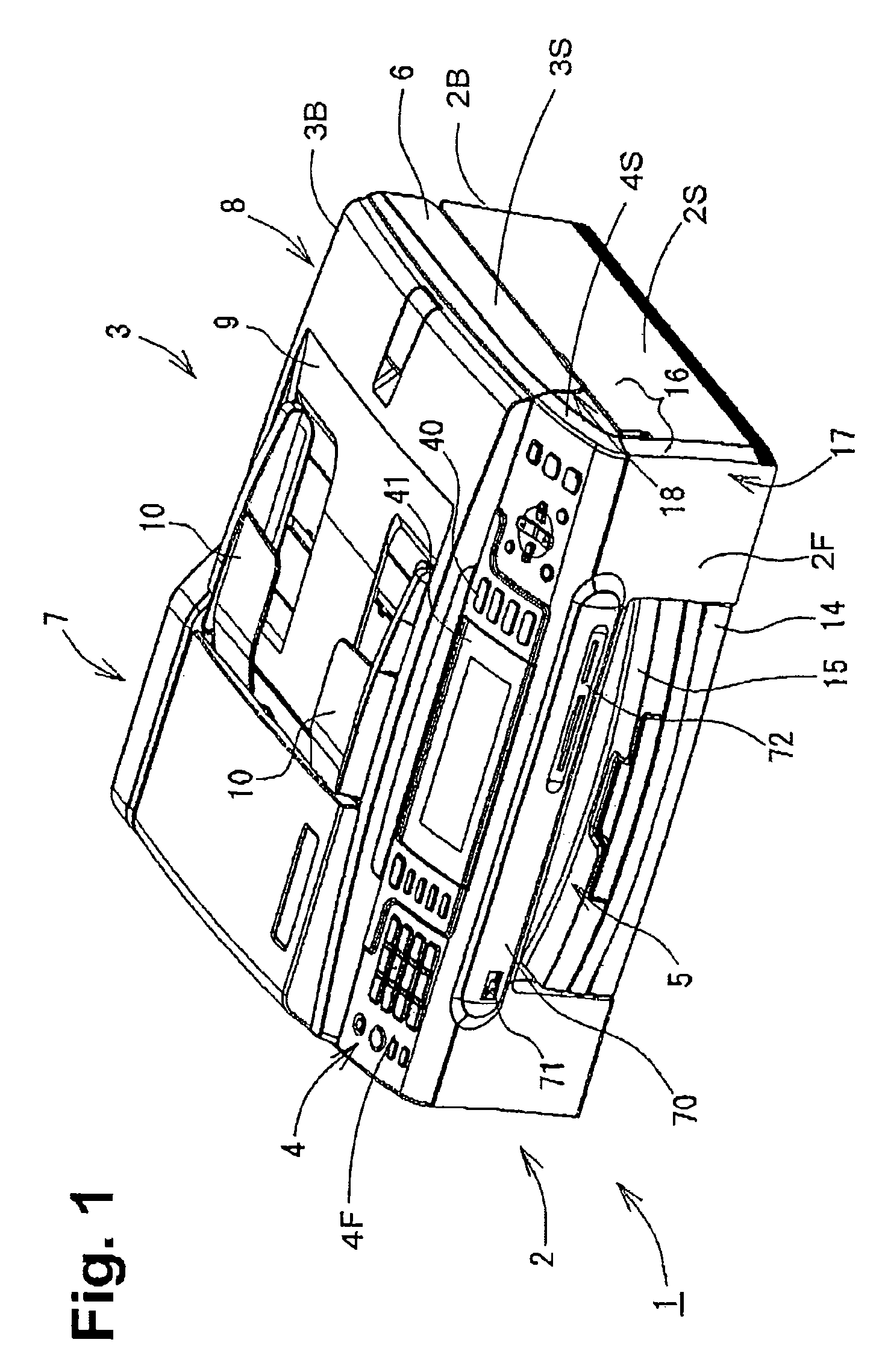
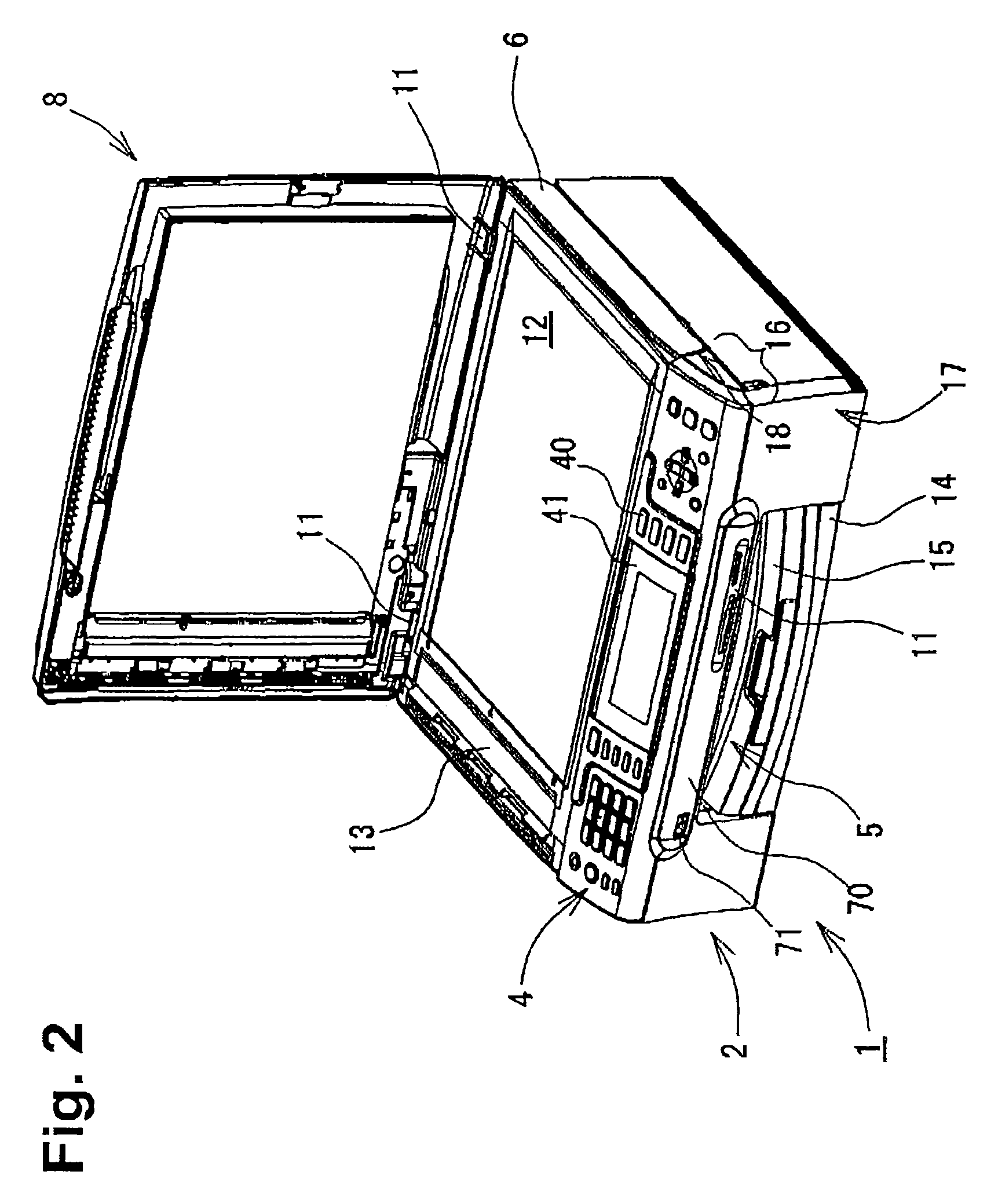
[0023]Embodiments of the present invention and their features and technical advantages may be understood by referring to FIGS. 1-10, like numerals being used for like corresponding portions in the various drawings.

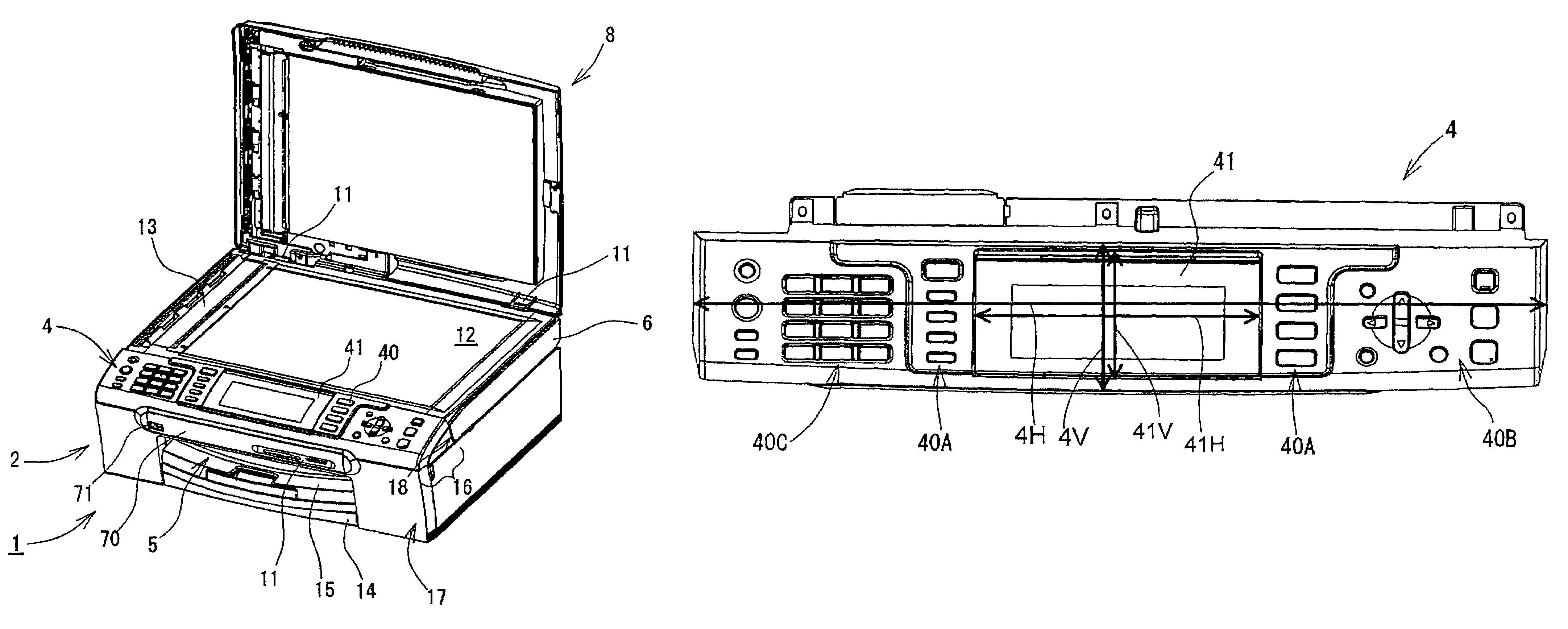
[0024]Referring to FIGS. 1 and 2, a multifunction device (MFD) 2 may comprise au image printer unit 2, an image scanner unit 3 mounted to the printer unit 2, and an operation panel 4 mounted on a front side of the scanner unit 3. The printer unit 2 may comprise a front wall 2F, a back wall 2B opposite the front wall 2F, and a pair of side walls 2S which are connected and substantially perpendicular to each of the front wall 2F and the back wall 2B. A distance between the front wall 2F and the back wall 2B corresponds to a maximum depth dimension of the multifunction device 1. The scanner unit 3 may comprise a back wall 3B and a pair of side walls 3S. Each of the side walls 3S may be connected to the back wall 3B. The back wall 3B is continuous and substantially flush with ...


PUM


Abstract

A multifunction device includes an image scanning unit and an image printing unit. The multifunction device further includes au operation panel which is positioned on a front side of the image scanning unit. The operation panel includes a display portion. Each of the display portion and the operation panel has a horizontal center line and a vertical center line which is perpendicular to the horizontal center line. A length of the vertical center line of the display portion is about equal to a length of the vertical center line of the operation panel. A ratio of a length of the horizontal center line of the display portion to the length of the vertical center line of the display portion is greater than 4 / 3.

Description

CROSS REFERENCE TO RELATED APPLICATION[0001]The present application claims priority from Japanese Patent Application No. 2006-051354, which was filed on Feb. 27, 2006, the disclosure of which is incorporated herein by reference in its entirety.FIELD OF THE INVENTION[0002]The present invention relates to a multifunction device which has an image printing unit, an image scanning unit mounted to the image printing unit, and an operation panel.BACKGROUND OF THE INVENTION[0003]A known multifunction device includes a plurality of units, such as a scanning unit and an image printing unit, which perform a plurality of different functions, such as a copying function, a printing function, a scanning function, and a facsimile function. For example, the image printing unit may perform the printing function and / or a facsimile receiving function, and the image scanning unit may perform the copying function, the scanning function, and / or a facsimile sending function. The known multifunction device...

Claims


Application Information

Patent Timeline
Patent Type & Authority Patents(United States)
IPC IPC(8): H04N1/04
CPCH04N1/00408H04N1/00519
Inventor IKENO, TAKAHIRODESHIMARU, TERUOSATO, TATSUYA
Owner BROTHER KOGYO KK
Why Eureka
Try Eureka