Thermodynamic machine and method for absorbing heat

a technology of thermodynamic machines and heat absorption, which is applied in the direction of refrigeration machines, refrigeration components, light and heating apparatus, etc., can solve the problems of high heat emission profit, large construction volume, and high cost of adsorption and absorption refrigeration devices, so as to reduce construction costs and reduce construction costs. , the effect of increasing the reliability of the compressor

Inactive Publication Date: 2010-11-09
MAKATEC GMBH
View PDF12 Cites 18 Cited by
  • Summary
  • Abstract
  • Description
  • Claims
  • Application Information

AI Technical Summary

Benefits of technology

[0020]With the present invention, based on the design of the thermodynamic machine, a mechanical robust process for refrigeration and for related tasks is provided. The mentioned process can be used for example for refrigerators and heat pumps, as well as similar installations. A process / method with the characteristics of the invented thermodynamic machine has the advantage that—by virtue of its mechanical robustness—it can be used for mobile as well as for stationary applications.
[0021]In the at least one thermodynamic device, refrigerator or heat supplying device being a main part of the thermodynamic machine, two fluid phases are separated by membranes / membrane components. In absorption refrigerators / heat pumps as well the absorber and the desorber may be configured as membrane devices. The membrane device is mechanical shocks resistant. In the membrane absorber and / or the membrane desorber a forced convection rules, so that—compared to conventional absorption devices with free fluid falling films—a significantly increased heat transport is given. Compared to a conventional absorber / desorber, the construction volume is reduced. Moreover, beside the increased transport characteristic, this is also related to the very high specific interphase area of up to 10000 m2 / m3, which can be achieved by modern membranes. A simultaneous cooling or heating in the membrane components causes further advantages. A very interesting alternative is the realisation of a heat exchange between solvent and cooling medium in the membrane absorber
[0023]Likewise, the membrane components can also be used for the evaporator or condenser in the absorption and compression devices. In compression devices, as an example, the reliability of the compressor can be increased, in case that exceptional mechanical shocks are expected to turn up.
[0024]By using plastics for the membranes and the device housing, a very low cost production is possible. If high thermal stress is expected—for example for a desorber—ceramic pore-membranes can be used.

Problems solved by technology

The same process is performed by heating pumps; however, here the profit comes from the heat emission at high temperature.
In addition adsorption and absorption refrigeration devices require higher investment costs and show up a bigger construction volume and a higher weight than compression cooling devices.
When in an absorption refrigerator a volatile solvent such as water is used, the required rectification increases the investment costs and the construction volume further.
Most of the investment costs of an absorption refrigerator are attributed to the heat transmitters.
Because of their lack of mechanical robustness nowadays absorption refrigeration devices cannot be used in mobile sectors.
This lack of mechanical robustness is related to the fact that in devices with liquid films, the liquid wetting of the heat exchanger surface are negatively affected by mechanical shocks, because the liquid gets through the devices as a free falling film.
In adsorption refrigeration devices, the main problem is the low heat transfer in the adsorber and desorber, as in these devices, no liquid is included and therefore, only the mechanisms of the heat conduction in fixed beds and the gas flow are relevant for the heat transport This causes increased investment costs compared to an absorption refrigerator.
Too high investment costs and too big construction volume are main obstacles which obstruct a further spreading of the absorption refrigeration technology and lead to the fact, that even in case that cheap energy is available—like waste heat—compression cooling devices are often preferred with the main disadvantage of consuming high quality mechanical energy.

Method used


Image

  • Thermodynamic machine and method for absorbing heat
  • Thermodynamic machine and method for absorbing heat
  • Thermodynamic machine and method for absorbing heat

Examples


Embodiment Construction

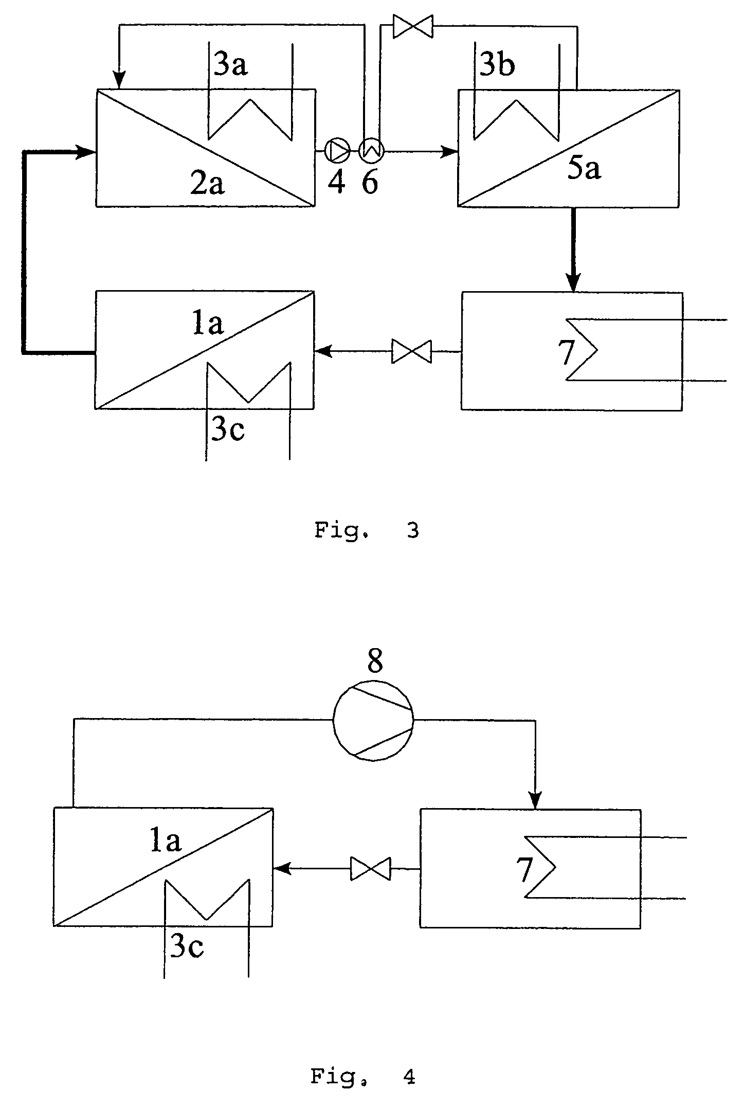
[0035]In FIGS. 1 to 5, various alternatives of the present invention are illustrated. The process compliant with the invention can be used in any case where phase transition occurs with heat exchange on different temperature levels and with the environment.

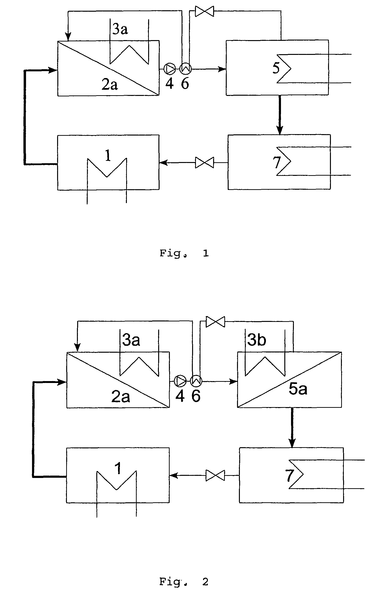
[0036]FIG. 1 shows a schematic representation of a refrigeration device—in accordance with the invention—with cooled membrane absorber. In a conventional evaporator 1, the cooling agent evaporates with heat absorption. The vapor flows into a membrane device 2a, in which, after transit through the membrane, it will be absorbed by a solvent. By virtue of the better mass transfer pore-membranes are used preferentially in the membrane absorber 2a.

[0037]For cooling of the solution agent the membrane absorber contains additionally a heat exchanger 3a, with a cooling medium flowing inside. The rich solution is pumped by a solution pump 4 to a conventional desorber 5, in which the cooling agent vaporises by heat addition. The solvent is ...


PUM


Abstract

A thermodynamic machine for the absorption and emission of heat at different temperatures has at least one thermodynamic device with at least one membrane separating a gas phase and a liquid phase provided for transport of heat, wherein the at least one membrane is permeable for at least one component contained in the gas and liquid phases. The at least one membrane is a porous membrane or a solution diffusion membrane or a modification of the porous membrane or a modification of the solution diffusion membrane.

Description

BACKGROUND OF THE INVENTION[0001]1. Field of the Invention[0002]The present invention relates to a thermodynamic apparatus and a method for the absorption and emission of heat, wherein at least one temperature during heat emission is located above at least one temperature during heat absorption.[0003]2. Prior Art[0004]One conventional technology for the production of cooling energy in air-conditioning and for cooling purposes are mechanically driven compression cooling devices. As an alternative, also absorption refrigeration devices with conventional tube bundle or plate absorbers are used. Recently, also adsorption cooling devices are developed based on zeolites, with a similar working process like absorption refrigeration devices.[0005]Refrigeration devices have the task to absorb heat at low temperatures and to emit heat at high temperatures again. The profit is the absorption of heat at low temperature. The same process is performed by heating pumps; however, here the profit co...

Claims


Application Information

Patent Timeline
Patent Type & Authority Patents(United States)
IPC IPC(8): F25B15/00F25B15/14
CPCF25B15/14Y02B30/62Y02A30/27
Inventor WEIMER, THOMASHACKNER, MICHAELHASSE, HANSSTROH, NORBERTWALITZA, ECKEHART
Owner MAKATEC GMBH
Why Eureka
Try Eureka