Armrest device in a chair

a technology for armrests and chairs, which is applied in the direction of chairs, vehicle components, vehicle arrangements, etc., can solve the problems of increasing the number of parts, increasing the number of movements of the armrest base plate, and increasing the complexity of assembly, so as to reduce the vertical size, and reduce the number of movements.

Inactive Publication Date: 2010-11-09
OKAMURA CORP
View PDF15 Cites 77 Cited by
  • Summary
  • Abstract
  • Description
  • Claims
  • Application Information

AI Technical Summary

Benefits of technology

[0014]To overcome the disadvantages in the prior art, it is an object of the invention to provide an armrest device in a chair in which an armrest base plate can be moved stably and smoothly, the parts being reduced in number and assembled easily.
[0016]It is a further object of the invention to provide an armrest device in a chair in which the device is unlikely to be broken or deformed even if excessive force acts on an operating lever.
[0017]It is yet another object of the invention to provide an armrest height adjuster in a chair in which the parts are assembled without screws, an intermediate tube being prevented from being released after assembling.

Problems solved by technology

However, the grooves on the side edge of the elongate hole make movement of the armrest base plate unsmooth.
In JP2005-211245A, a pair of engagement pins is provided on each side of the elastic member and pressed onto the side edge of the elongate hole, so that the number of parts increases and assembling becomes more complicated.
But the structure therefor makes the armrest device larger, and there are problems that the number of parts increases and its assembling becomes more complicated.
During operation, excessive force acts onto the operating portion, so that the pivot and / or extension is likely to be easily deformed or damaged.
If the pin should be caught on one of the engagement holes to make the operating rod impossible to return, the knob will not be operative.
Means for limiting back-and-forth movement of the knob becomes more complicated.
To prevent such problem, the guide sleeve is fixed to the armrest support rod with screws, but heads of the screws are exposed to make its appearance poorer and working for mounting the screws is more complicated to make its assembly more difficult.

Method used


Image

  • Armrest device in a chair
  • Armrest device in a chair
  • Armrest device in a chair

Examples


Embodiment Construction

[0037]An embodiment of the present invention will be described with respect to the drawings.

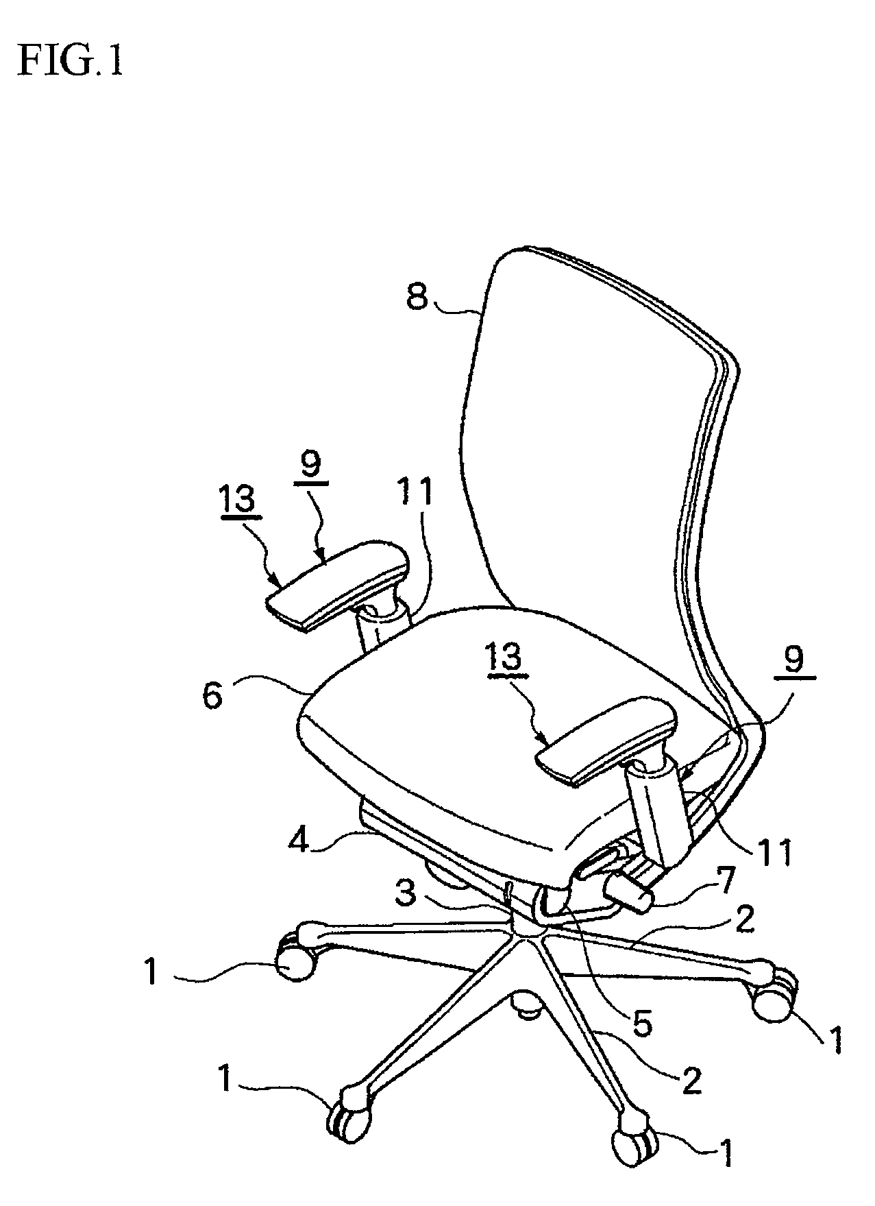
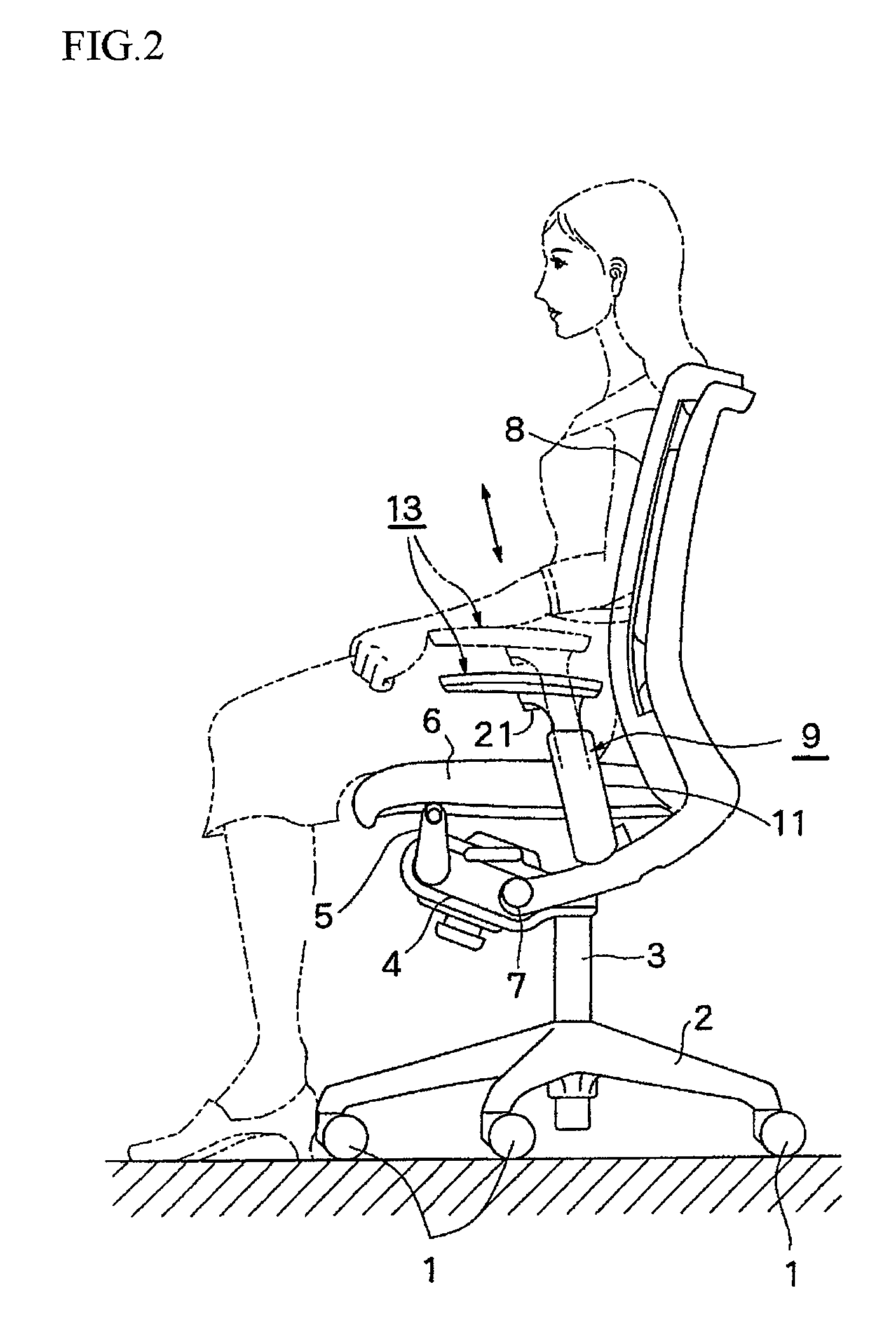
[0038]FIG. 1 is a perspective view of an embodiment of a chair comprising an armrest device according to the present invention, and FIG. 2 is a left side view thereof.

[0039]The chair comprises a leg 3 that extends upright from five radially-extending feet 2 each of which comprises a caster 1 at the end; a support base 4 at the upper end of the leg 3; a seat 6 supported by a support link 5 over the support base 4; and a backrest 8 pivotally mounted to the support base 4 with a horizontal shaft 7 so that the backrest 8 may be inclined rearward; and an armrest device 9 extending upright from each side of the seat 6. The armrest device 9 may extend upright from one side of the seat 6.

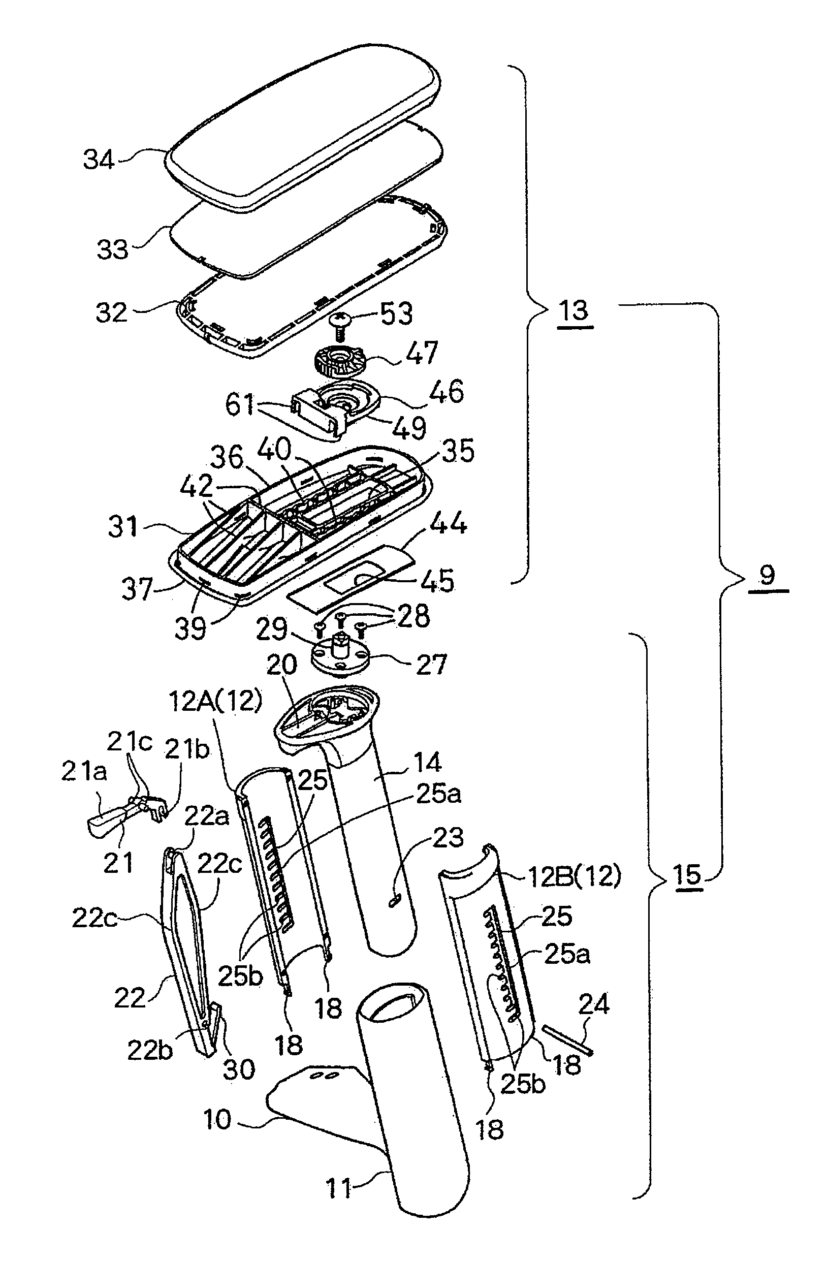
[0040]FIGS. 3-8 show the details of the armrest device 9.

[0041]The armrest device 9 comprises an armrest-support tube 11 in which a bracket 10 extending from the inside at the lower end is fixed to the lower surface ...


PUM


Abstract

An armrest device comprises an armrest base plate on the upper end of an armrest support rod. A support block is provided on the armrest base plate. An engagement portion of the support block engages in a slot of the armrest base plate. A plurality of grooves are formed on a projection along the slot. An elastic tongue of the support block engages with the projection to allow the armrest base plate to slide back and forth smoothly.The armrest support rod is surrounded by an intermediate tube and an armrest support tube. A turning lever in the armrest support rod is pivotally mounted to an operating lever on the upper end of the armrest support rod. A pin which passes through a hole of the turning lever engages in an opening of the intermediate tube. The opening comprises a vertical elongate portion and a plurality of horizontal engagement portions. The pin selectively engages in any one of the engagement portions to allow the armrest to be held at respective height.

Description

BACKGROUND OF THE INVENTION[0001]The present invention relates to an armrest device in a chair.[0002]JP2005-211245A and JP2002-51871A disclose an armrest device in which an elongate hole is formed in an armrest base plate, a plurality of grooves being formed on each edge of the elongate hole, an elastic member being provided to press the side edge of the elongate hole on a support provided on the upper end of an armrest support rod for supporting an armrest to allow the armrest base plate to move with respect to the armrest support rod, the elastic member elastically engaging in the groove to provide stepwise resistant force of the armrest base plate. However, the grooves on the side edge of the elongate hole make movement of the armrest base plate unsmooth.[0003]In JP2005-211245A, a pair of engagement pins is provided on each side of the elastic member and pressed onto the side edge of the elongate hole, so that the number of parts increases and assembling becomes more complicated....

Claims


Application Information

Patent Timeline
Patent Type & Authority Patents(United States)
IPC IPC(8): B60N2/46B60N2/75
CPCA47C1/03A47C1/0305A47C1/0308
Inventor ODA, YOUICHIROU
Owner OKAMURA CORP
Why Eureka
Try Eureka