
Receiving apparatus

a technology of receiving apparatus and receiving device, which is applied in the direction of electric signalling details, navigation instruments, instruments, etc., to achieve the effect of providing useful information to users

Inactive Publication Date: 2010-11-09
PANASONIC CORP
View PDF9 Cites 0 Cited by
  • Summary
  • Abstract
  • Description
  • Claims
  • Application Information

AI Technical Summary

Benefits of technology

[0009]This operation prevents a user from listening a broadcast interrupted by an unnecessary emergency broadcast. The receiving apparatus selectively reproduces traffic jam information occurring in the destination area the user moves to, thus effectively providing the user with useful information, such as the traffic jam information.

Problems solved by technology

In this case, the conventional receiving apparatus has a problem to delivering the emergency broadcasts, allowing the emergency broadcasts to often interrupt the broadcasts which the user listens to.

Method used


Image

  • Receiving apparatus
  • Receiving apparatus
  • Receiving apparatus

Examples


exemplary embodiment 1

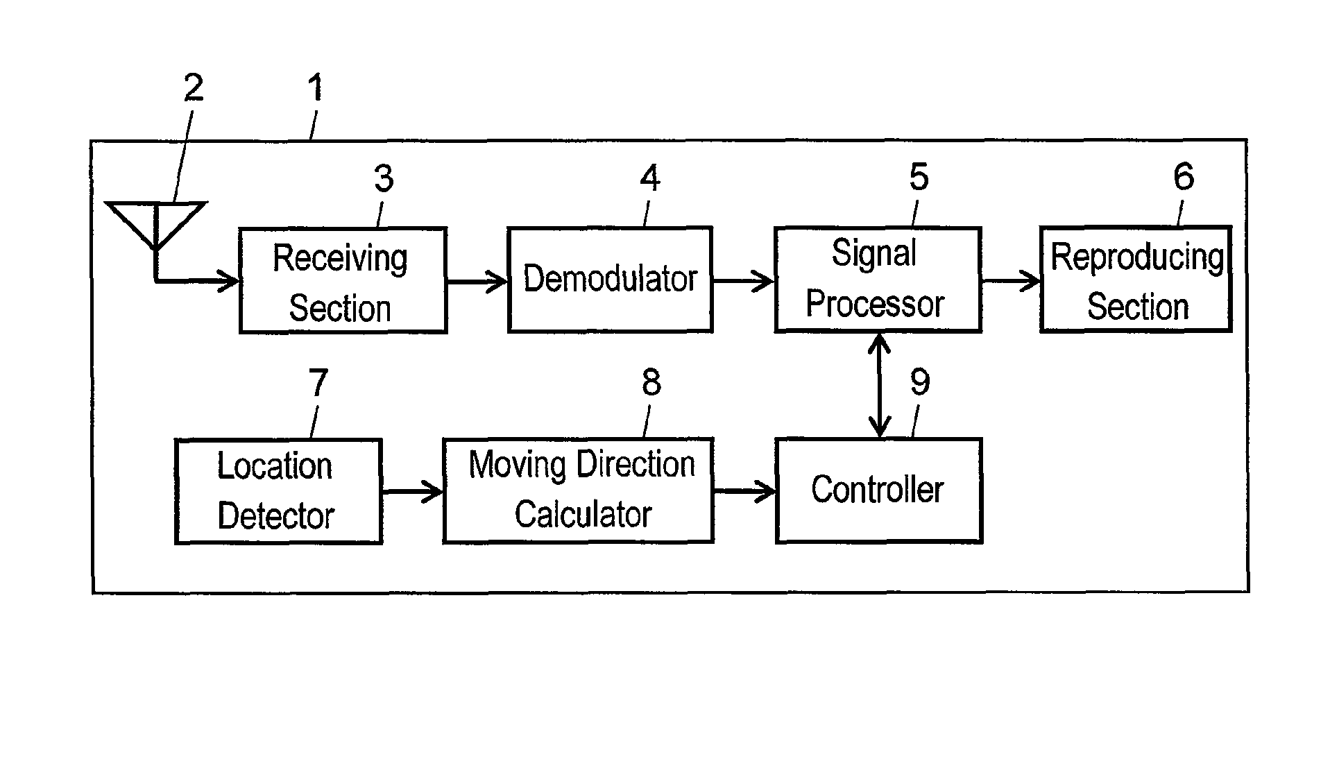
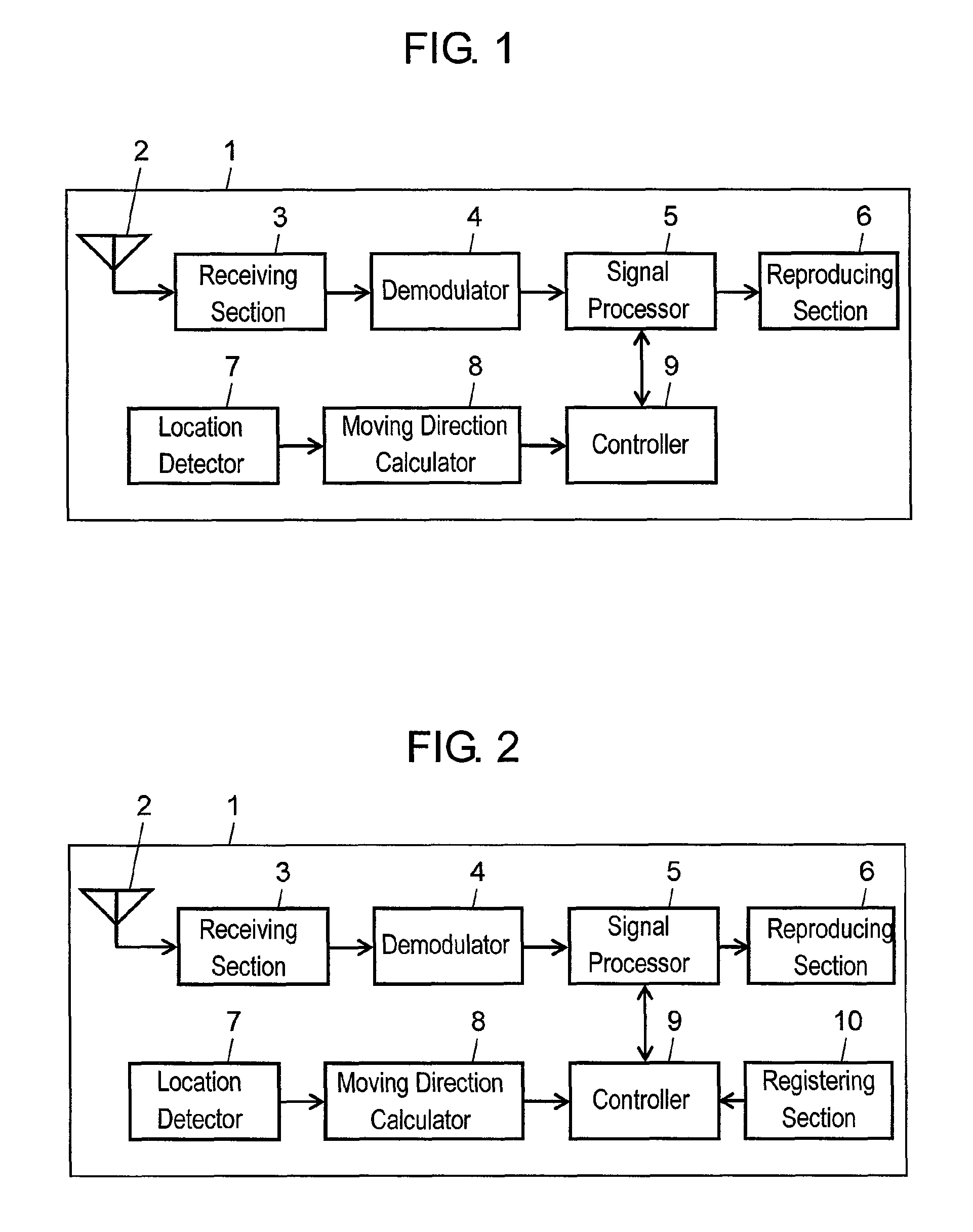
[0022]A receiving apparatus according to Exemplary Embodiment 1 will be described with reference to FIG. 1. FIG. 1 is a block diagram of the receiving apparatus according to Embodiment 1.

[0023]Receiving apparatus 1 shown in FIG. 1 is, for example, a radio tuner mounted to a vehicle. Receiving apparatus 1 includes antenna 2 and receiving section 3 connected to an output port of antenna 2. Demodulator 4, signal processor 5 and reproducing section 6 are connected to an output port of receiving section 3 in this order. Receiving apparatus 1 further includes location detector 7, moving direction calculator 8 connected to an output port of location detector 7, and controller 9 connected to an output port of moving direction calculator 8. Controller 9 is connected to signal processor 5.

[0024]Receiving apparatus 1 will be described in detail below.

[0025]Receiving section 3 receives a digital radio broadcast of digital audio broadcasting (DAB) system via antenna 2. The radio broadcast receiv...

exemplary embodiment 2

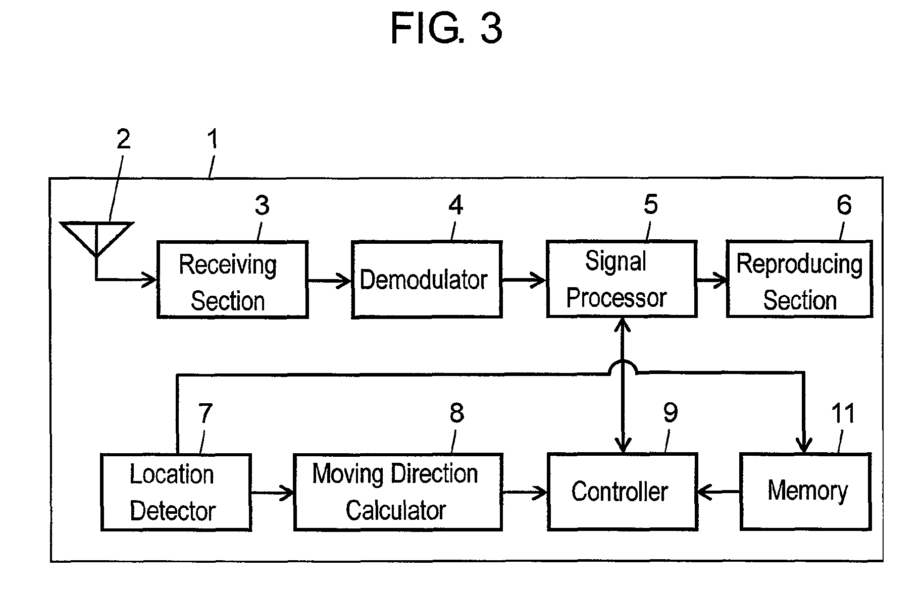
[0035]Exemplary Embodiment 2 will be described with reference to FIG. 2. Components identical to those of Embodiment 1 will not be described in detail, and characteristic feature will be described.

[0036]According to Embodiment 2 different from Embodiment 1, registering section 10 is connected to an input port of controller 9, as shown in FIG. 2.

[0037]A user registers area data of an arbitrary area with registering section 10. For example, the area data relates to the area the user often moves to, and contains data of the latitude and longitude of the area. The data of the latitude and longitude may be determined based on the name of the area input by the user.

[0038]Controller 9 allows reproducing section 6 to reproduce a part of or all of broadcast received by receiving section 3 selectively based on a moving direction of receiving apparatus 1 calculated by moving direction calculator 8 and on the area data registered in registering section 10.

[0039]An operation of controller 9 of r...


PUM


Abstract

A receiving apparatus includes a receiving section for receiving a broadcast. The apparatus further includes a location detector for detecting the location of the receiving apparatus, a moving direction calculator for calculating a moving direction of the receiving apparatus based on the location detected by the location detector, and a controller for allowing a reproducing section to reproduce a part of or all of the broadcast received by the receiving section selectively based on the moving direction calculated by the moving direction calculator.

Description

[0001]THIS APPLICATION IS A U.S. NATIONAL PHASE APPLICATION OF PCT INTERNATIONAL APPLICATION PCT / JP2006 / 322227.TECHNICAL FIELD[0002]The present invention relates to a receiving apparatus for receiving a broadcast.BACKGROUND ART[0003]A conventional receiving apparatus will be described below. In addition to ordinary broadcasts, television and radio broadcasts provide a user with emergency broadcasts including traffic information and various warnings. If the emergency broadcasts are delivered while the user is listening to the ordinary broadcasts, a conventional receiving apparatus reproduces the emergency broadcasts, allowing the emergency broadcasts to interrupt the ordinary broadcasts.[0004]Patent document 1 relates to the invention of the present application.[0005]Upon not being relevant to a destination area the user move to, emergency broadcasts, such as traffic information, may be unnecessary for the user. In this case, the conventional receiving apparatus has a problem to deli...

Claims


Application Information

Patent Timeline
Patent Type & Authority Patents(United States)
IPC IPC(8): G08B1/08G08G1/123G01C21/00
CPCH04H20/59H04H60/51H04H40/27
Inventor NISHIMIYA, YUSAKU
Owner PANASONIC CORP
Learn More