Tap apparatus for electrically interconnecting an electrical busway and switchgear, and system including the same

a technology of electrical busways and taps, which is applied in the direction of laminated busways, substations, non-enclosed substations, etc., can solve the problems of requiring dozens of square feet of space for such equipment, and corresponding labor and equipment costs

Inactive Publication Date: 2010-11-09
EATON CORP
View PDF12 Cites 18 Cited by
  • Summary
  • Abstract
  • Description
  • Claims
  • Application Information

AI Technical Summary

Problems solved by technology

This, however, has various disadvantages associated with corresponding labor and equipment costs, as well requiring dozens of square feet of space for that equipment.

Method used


Image

  • Tap apparatus for electrically interconnecting an electrical busway and switchgear, and system including the same
  • Tap apparatus for electrically interconnecting an electrical busway and switchgear, and system including the same
  • Tap apparatus for electrically interconnecting an electrical busway and switchgear, and system including the same

Examples


example 1

[0042]As shown in FIG. 8, the example bridge joint connection tap apparatus 2 enters the example IFS switchboard 8 from the side. The tap apparatus 2 is structured to be removeably coupled to the inside of the IFS switchboard 8, rather than being fixedly coupled, for example, to the outside of a conventional residential meter stack. This permits, for example, a contractor to remove the entire internal tap apparatus 2, position the IFS switchboard 8, and then re-install the internal tap apparatus 2 to the electrical busway 4. The resulting system is rated, for example and without limitation, for use up to 800 A.

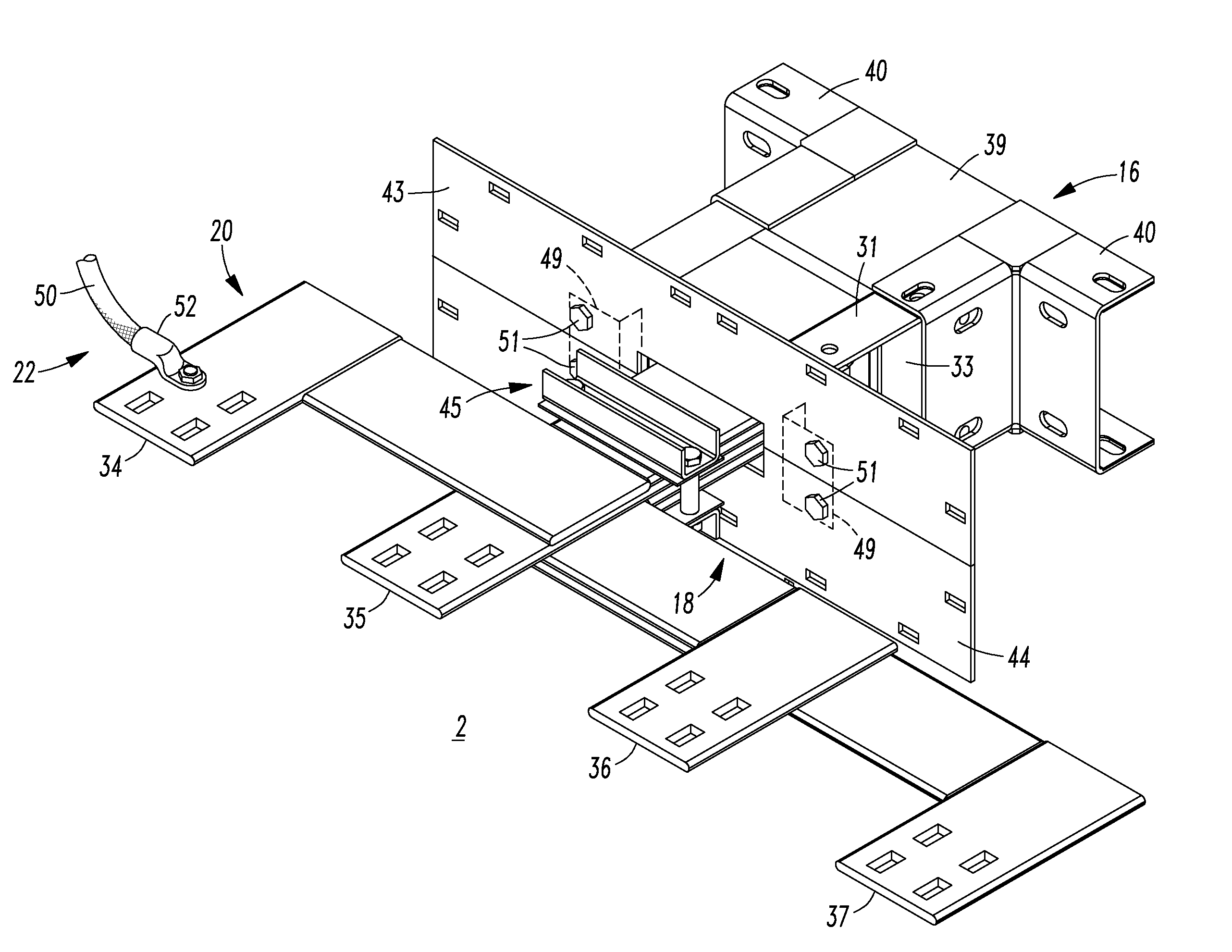
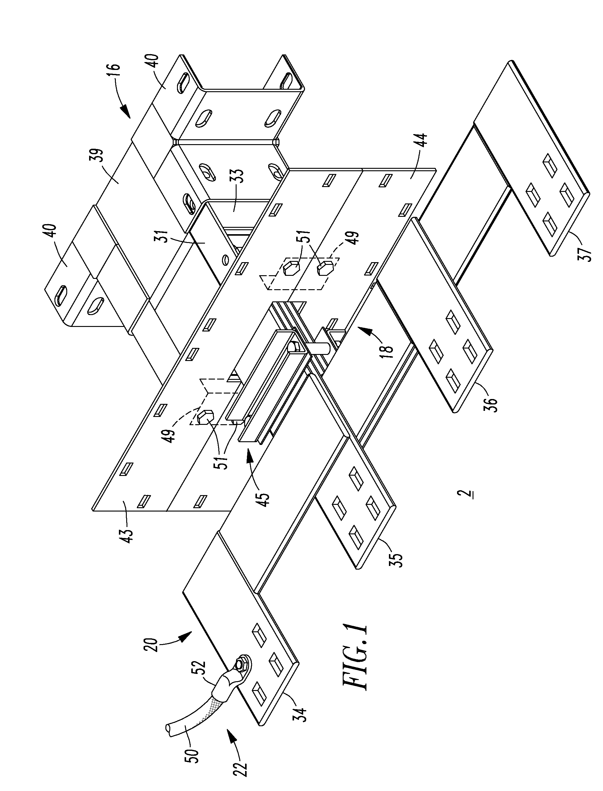
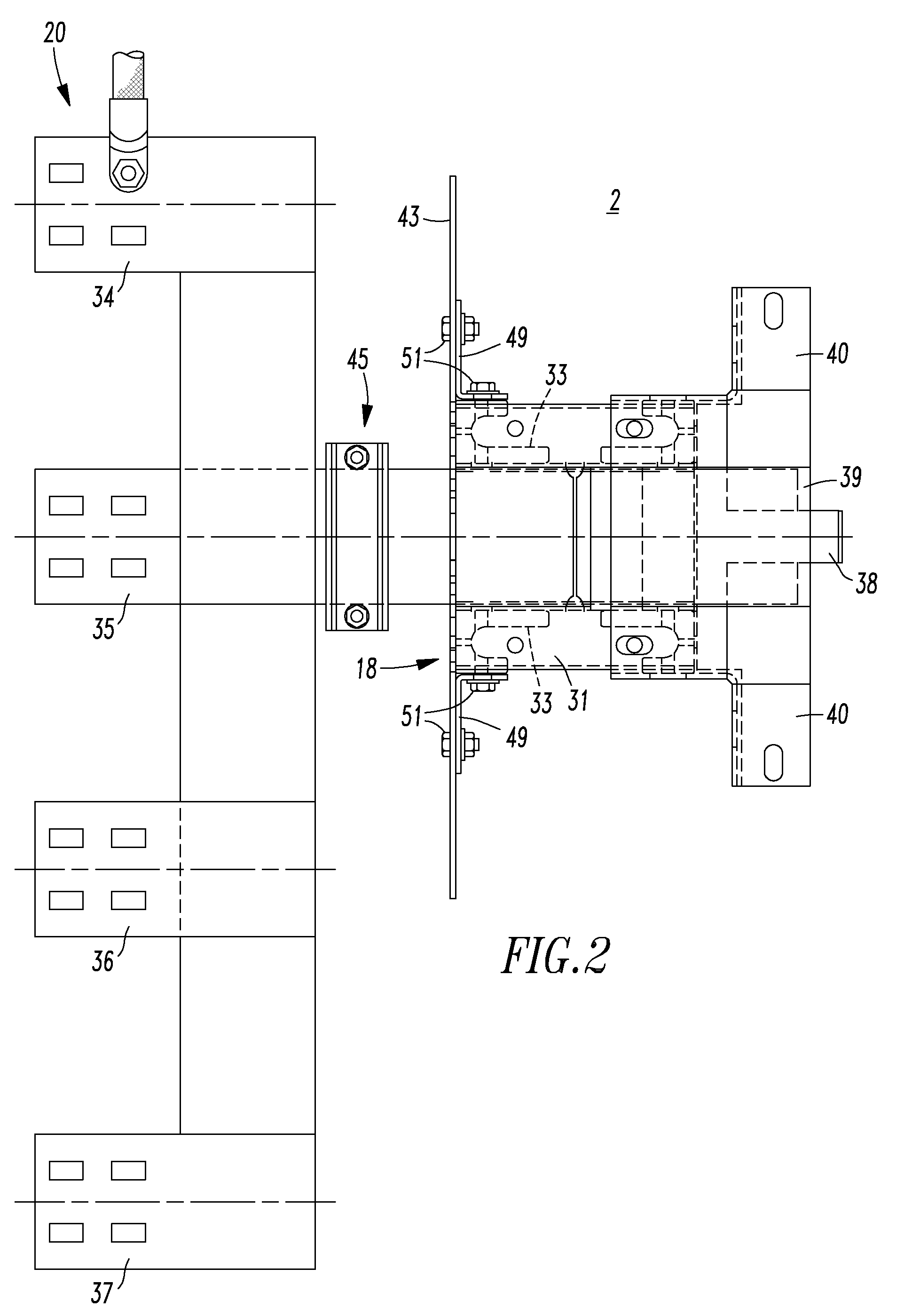
[0043]As shown in FIGS. 6 and 8, the example third portion 20 (FIG. 1) of the tap apparatus 2 is structured to receive the mechanical lugs 52 that enable the tap apparatus 2 to be electrically connected by the flexible electrical conductors 50 to, for example, the main circuit breaker 56 (e.g., without limitation, 480V) of the IFS switchboard 8.

[0044]Portions 16,18,20 of FIG. ...

example 2

[0045]Although FIGS. 6 and 8 show entry on a particular side of the example IFS switchboard 8, it will be appreciated that the disclosed tap apparatus 2 can provide entry on the opposite side or on the back thereof. Although not required, the front of the example IFS switchboard 8 is used for a door (not shown).

example 3

[0046]The disclosed tap apparatus 2 provides a removable tap that can advantageously be pre-positioned at a suitable location within the example electrical enclosure 8 (e.g., without limitation, the example IFS switchboard). The removable tap is installed from inside the electrical enclosure 8 in order to aid installation. Furthermore, the example tap apparatus 2 employs four lugs 52 and four flexible power cables 50 for internal electrical connections within the electrical enclosure 8. This permits the tap apparatus 2 to mount from the inside of the electrical enclosure 8 after this electrical enclosure has already been set in place proximate the electrical busway 4.


PUM


Abstract

A system includes an electrical busway, an electrical enclosure enclosing an electrical apparatus, the electrical enclosure including an interior and a mounting portion with an opening therethrough; and a tap apparatus electrically interconnecting the electrical busway and the electrical apparatus. The tap apparatus includes a first portion electrically interconnected with the electrical busway through the opening of the mounting portion, a second portion removeably coupled to the mounting portion of the electrical enclosure from the interior of the electrical enclosure, and a third portion including a flexible electrical connection electrically interconnected with the electrical apparatus.

Description

BACKGROUND[0001]1. Field[0002]The disclosed concept pertains generally to electrical busways and, more particularly, to tap apparatus for such electrical busways. The disclosed concept also pertains to systems including an electrical busway and an electrical enclosure electrically interconnected with the electrical busway.[0003]2. Background Information[0004]Various electrical components are defined by, and subject to, regulatory requirements. For example and without limitation, the Underwriter's Laboratory (UL) defines an “electrical busway”, at UL 857, as a grounded metal enclosure containing factory mounted conductors that are usually copper or aluminum bars, rods, or tubes. Similarly, the National Electric Code (NEC) defines an electrical busway as a grounded metal enclosure containing factory mounted, bare, or insulated conductors, which are usually copper or aluminum bars, rods, or tubes.[0005]Typically, electrical busways include a plurality of electrical conductors (e.g., wi...

Claims


Application Information

Patent Timeline
Patent Type & Authority Patents(United States)
IPC IPC(8): H01R9/22
CPCH02B1/20H02G5/005
Inventor STRONG, RYAN J.TEAKEN, MARK T.
Owner EATON CORP
Why Eureka
Try Eureka