Supercharge Your Innovation With Domain-Expert AI Agents!

Data carrier and data carrier system

a data carrier and data carrier technology, applied in the field of data carrier and data carrier system, can solve the problems of increasing the number of terminals, the proportion of the cost of forming terminals required for performing contact communication, and the proportion of the risk of contact failur

Inactive Publication Date: 2010-11-16
YOSHIKAWA RF SYST
View PDF11 Cites 2 Cited by
  • Summary
  • Abstract
  • Description
  • Claims
  • Application Information

AI Technical Summary

Benefits of technology

Reduces manufacturing costs and minimizes contact failures by enabling both RF and contact serial communication with a reduced number of terminals, simplifying control circuits and authentication processes.

Problems solved by technology

The cost for forming terminals required for performing contact communication increases in proportion to the number of terminals to be formed.
Furthermore, when contact communication is performed, the risk of occurrence of contact failure increases in proportion to the number of terminals.

Method used


Image

  • Data carrier and data carrier system
  • Data carrier and data carrier system
  • Data carrier and data carrier system

Examples


first embodiment

[0049]An embodiment of the data carrier system of the present invention will be described below with reference to drawings.

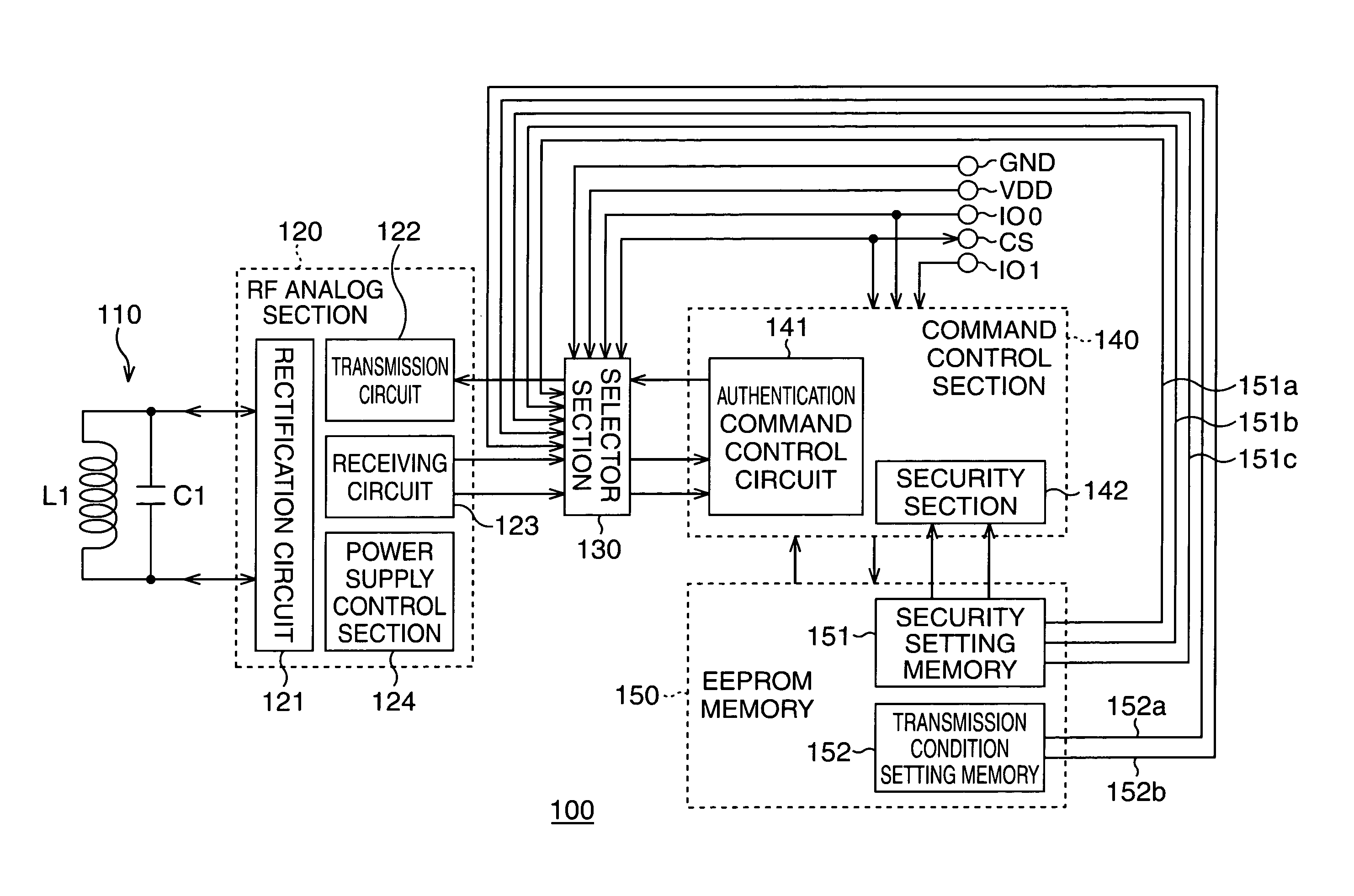
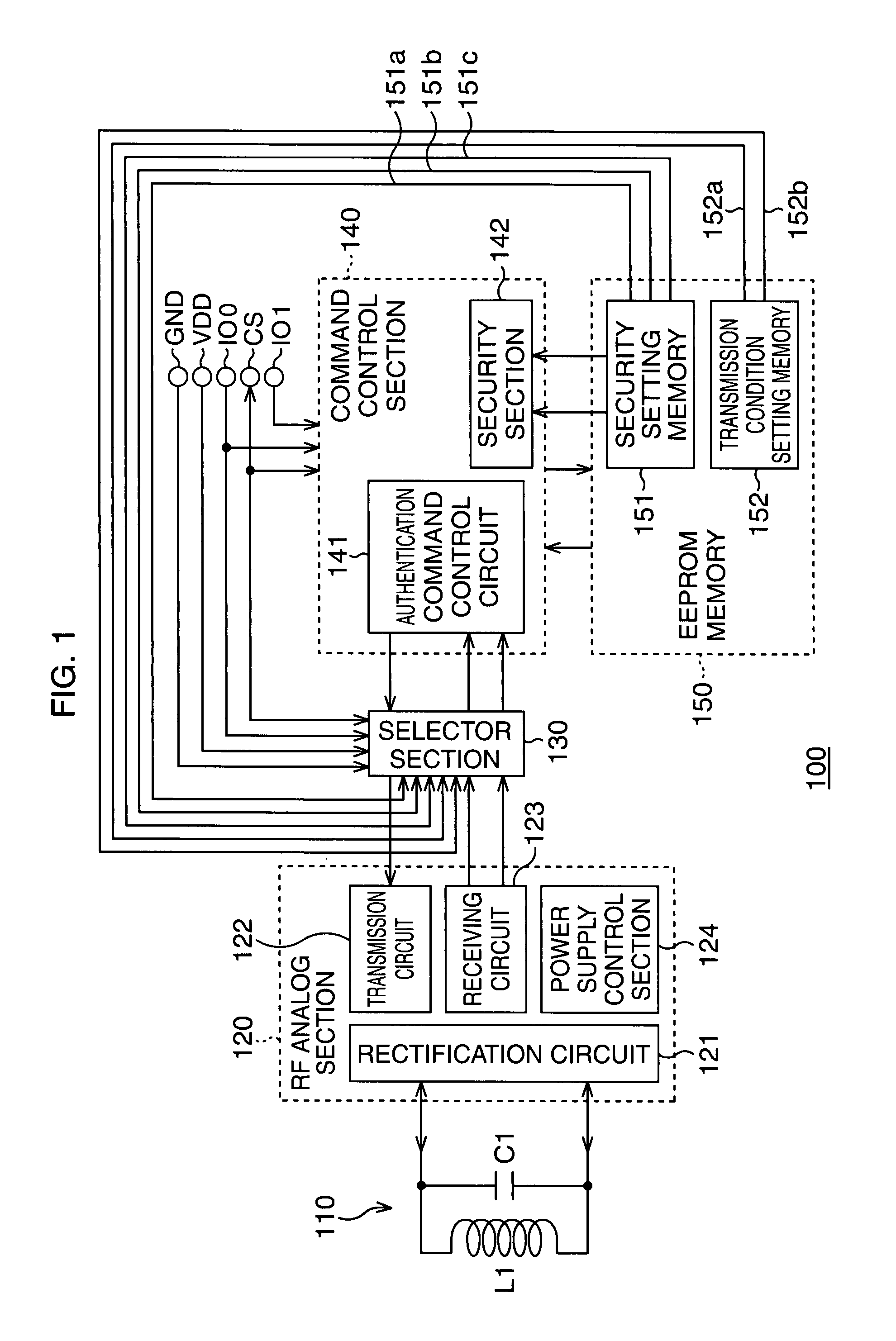
[0050]As shown in FIG. 1, a data carrier 100 of this embodiment is configured by an antenna circuit 110, an RF analog section 120, a selector section 130, a command control section 140, a storage section 150 (EEPROM memory), a first contact terminal CS, a second contact terminal IO0, a third contact terminal VDD, a fourth contact terminal GND, a data input / output terminal IO1 and the like. Here, as the first contact terminal CS, the third contact terminal VDD or the fourth contact terminal GND can be used in common, and the first contact terminal CS can be regarded as an internal terminal. Therefore, it is the four terminals of the second contact terminal IO0, the third contact terminal VDD, the fourth contact terminal GND and the data input / output terminal IO1 that are used for performing contact communication.

[0051]Due to such a configuration, the data carrier...

second embodiment

[0118]Next, Second Embodiment of the present invention will be described with reference to FIG. 10.

[0119]In the case of a complex data carrier, since VDH≧VDD is satisfied at the time of the non-contact operation, a circuit which uses the rectified voltage VDH as power supply can operate, as described before with reference to FIG. 12. In the example of FIG. 12, the reference voltage generation circuit 1241 can operate.

[0120]However, at the time of the contact operation, “the rectified voltage VDH=0” is satisfied, and voltage is not supplied in the direction from VDD to VDH. Therefore, there is a problem that the reference voltage generation circuit 1241 does not operate at the time of the contact operation. In order to avoid this problem, it is necessary to provide a reference voltage generation circuit 1241 which uses VDD as operating power supply. However, addition of a reference voltage generation circuit 1241 causes a problem of increasing the circuit scale.

[0121]Accordingly, in ...


PUM


Abstract

Both RF communication and contact serial communication can be performed with the use of: communication protocol storage unit for storing a communication protocol for performing communication with an external communication apparatus; a coil terminal section provided with two coil terminals for performing communication with the external communication apparatus with an RF signal; a contact communication terminal section provided with a first communication terminal, a second communication terminal, a power supply voltage terminal and a ground terminal as contact communication terminals for performing contact communication with the external communication apparatus; and connection control unit for causing the power supply voltage terminal and a power supply of an internal switch circuit to be in contact or non-contact with each other depending on the level of voltage applied to the first and second communication terminals.

Description

CROSS-REFERENCE TO RELATED APPLICATIONS[0001]This application is based upon and claims the benefit of priority from the prior Japanese Patent Application Nos. 2006-296512, filed on Oct. 31, 2006 and 2007-247642, filed on Sep. 25, 2007, the entire contents of which are incorporated herein by reference.BACKGROUND OF THE INVENTION[0002]1. Field of the Invention[0003]The present invention relates to a data carrier and a data carrier system, and more particularly, to a technique preferable for being used for performing both RF communication and contact serial communication between a data carrier and a reader / writer apparatus.[0004]2. Description of the Related Art[0005]Conventionally, a data carrier system has been put to practical use in various fields which is configured by a data carrier and a reader / writer apparatus and in which data is given and received between the data carrier and the reader / writer apparatus. In such a data carrier system, the data carrier obtains operating power ...

Claims


Application Information

Patent Timeline
Patent Type & Authority Patents(United States)
IPC IPC(8): G08B26/00G05B19/00
CPCG06K7/0008G06K19/07G06K19/077G06K19/07769
Inventor SUGAWARA, YOSHIKAZUYASUDA, NAOTAKAKUBO, TAKASHISAWADA, KIKUZOTANG, YUMING
Owner YOSHIKAWA RF SYST
Features
  • R&D
  • Intellectual Property
  • Life Sciences
  • Materials
  • Tech Scout
  • Unparalleled Data Quality
  • Higher Quality Content
  • 60% Fewer Hallucinations
Learn More