Lead retention assembly

a technology of retention assembly and lead, which is applied in the field of medical devices, can solve the problems of awkward use of torque wrenches to tighten the set screw of a device implanted in a patient, and achieve the effect of reducing the surgical steps during the implantation of an electrical signal generator system

Inactive Publication Date: 2010-11-16
MEDTRONIC INC
View PDF7 Cites 21 Cited by
  • Summary
  • Abstract
  • Description
  • Claims
  • Application Information

AI Technical Summary

Benefits of technology

[0007]By providing a lead retention assembly that (i) allows a lead to be inserted upon application of a compressive force and (ii) engages and retains the lead upon release of the compressive force, surgical steps during implantation of an electrical signal generator system may be reduced. For example, steps of tightening a small set screw with a torque wrench and electrically isolating the set screw by suturing a boot may be eliminated. These and other advantages will be readily understood from the following detailed descriptions when read in conjunction with the accompanying drawings.

Problems solved by technology

Use of a torque wrench to tighten a set screw of a device implanted in a patient can be awkward.

Method used


Image

  • Lead retention assembly
  • Lead retention assembly
  • Lead retention assembly

Examples


Embodiment Construction

[0015]In the following detailed description, reference is made to the accompanying drawings that form a part hereof, and in which are shown by way of illustration several specific embodiments of devices, systems and methods. It is to be understood that other embodiments are contemplated and may be made without departing from the scope of spirit of the present invention. The following detailed description, therefore, is not to be taken in a limiting sense.

[0016]All scientific and technical terms used herein have meanings commonly used in the art unless otherwise specified. The definitions provided herein are to facilitate understanding of certain terms used frequently herein and are not meant to limit the scope of the present disclosure.

[0017]As used in this specification and the appended claims, the singular forms “a”, “an”, and “the” encompass embodiments having plural referents, unless the content clearly dictates otherwise. As used in this specification and the appended claims, t...


PUM


Abstract

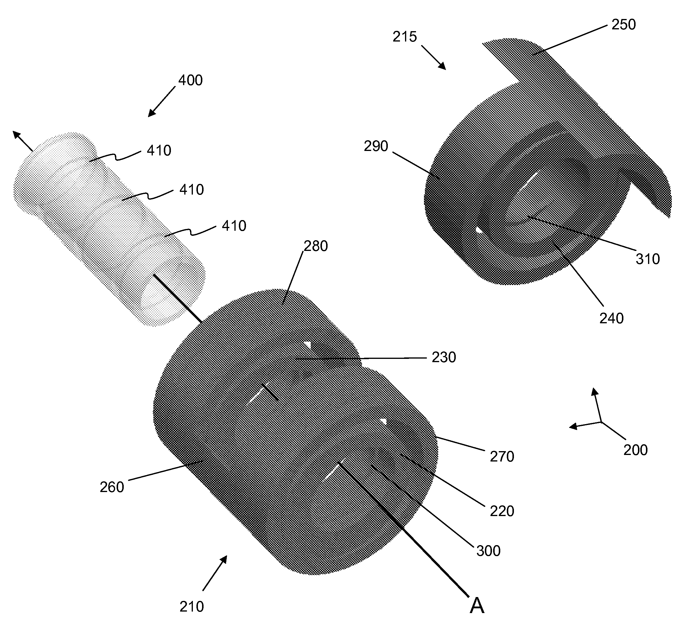
A lead retention assembly includes first, second and third retention members. The first retention member defines a first opening configured to receive a lead body. The second retention member is longitudinally spaced apart from the first retention member and defines a second opening configured to receive the lead body. The first and second retention members are substantially aligned along a first axis. The third retention member defines a third opening configured to receive the lead body. The third retention member is disposed between the first and second retention members and is biased in a position such that the third opening is substantially centered on a second axis. Upon application of a compressive force, the third retention member is moveable to a position such that the first, second, and third openings are substantially aligned along a common axis, allowing the lead body to be inserted within the first, second and third openings.

Description

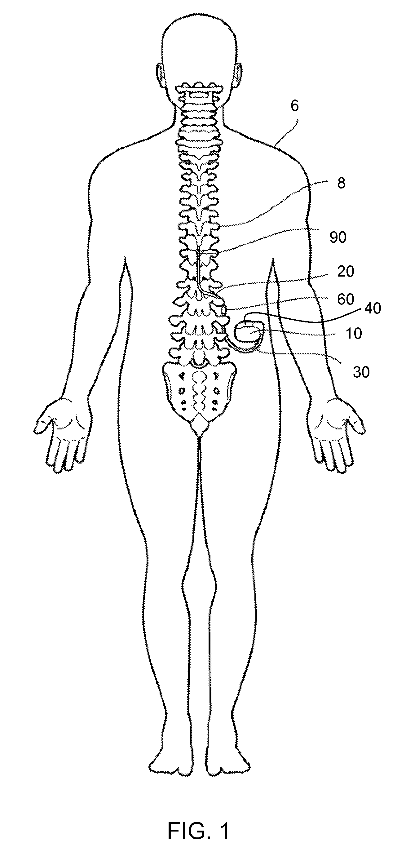
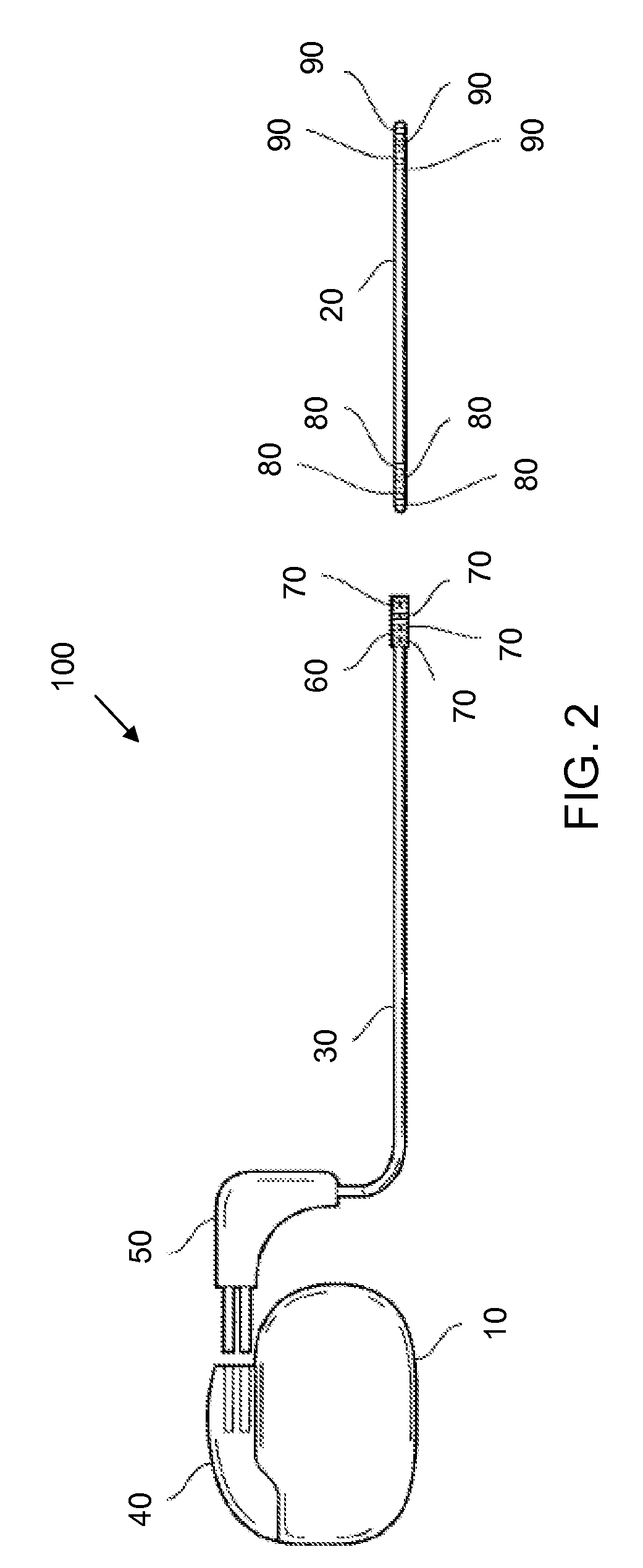
FIELD[0001]This application relates to medical devices, more particularly implantable leads and retention assemblies for coupling leads to lead extensions or electrical signal generators.BACKGROUND[0002]Implantable electrical signal generators, such as pacemakers, defibrillators, neurostimulators, and the like, have been used to treat a variety of diseases. Such devices generate electrical signals that are transferred to a patient's tissue through electrodes disposed on a distal end portion of a lead. The proximal end portion of the lead typically contains a number of connector rings corresponding to the number of electrodes. Conductors run within and along the lead body and electrically couple the connectors to the electrodes. The proximal end portion of the lead is inserted into connector of a signal generator such that electrical contact is made between discrete contacts in the connector portion and the connector rings of the lead. Alternatively, the lead is inserted into connect...

Claims


Application Information

Patent Timeline
Patent Type & Authority Patents(United States)
IPC IPC(8): A61N1/375
CPCA61N1/3752H01R4/4845H01R2201/12H01R4/48455
Inventor ALEXANDER, JAMES A.SAGE, SHAHN
Owner MEDTRONIC INC
Why Eureka
Try Eureka