Rotary engine with vanes rotatable by compressed gas injected thereon

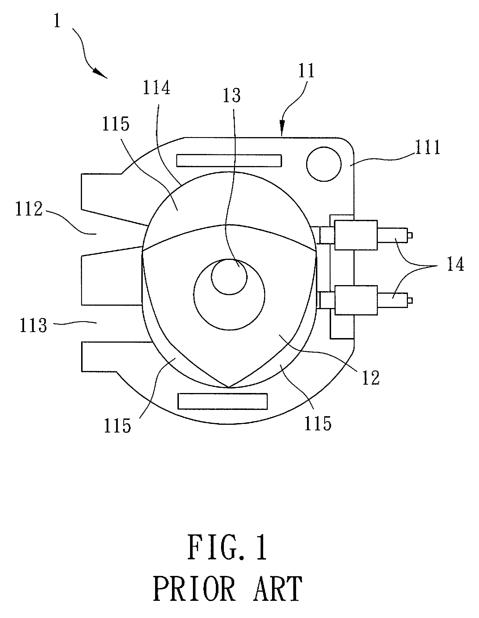
a rotary engine and compressed gas technology, applied in the field of engines, can solve problems such as unstable engine running b>1/b>, and achieve the effect of stable operation

Inactive Publication Date: 2010-12-07
WANG SERN BEAN
View PDF26 Cites 37 Cited by
  • Summary
  • Abstract
  • Description
  • Claims
  • Application Information

AI Technical Summary

Benefits of technology

[0010]The object of this invention is to provide a high-efficiency rotary engine that can run stably.

Problems solved by technology

As a result, running of the engine 1 is unstable.

Method used


Image

  • Rotary engine with vanes rotatable by compressed gas injected thereon
  • Rotary engine with vanes rotatable by compressed gas injected thereon
  • Rotary engine with vanes rotatable by compressed gas injected thereon

Examples


Embodiment Construction

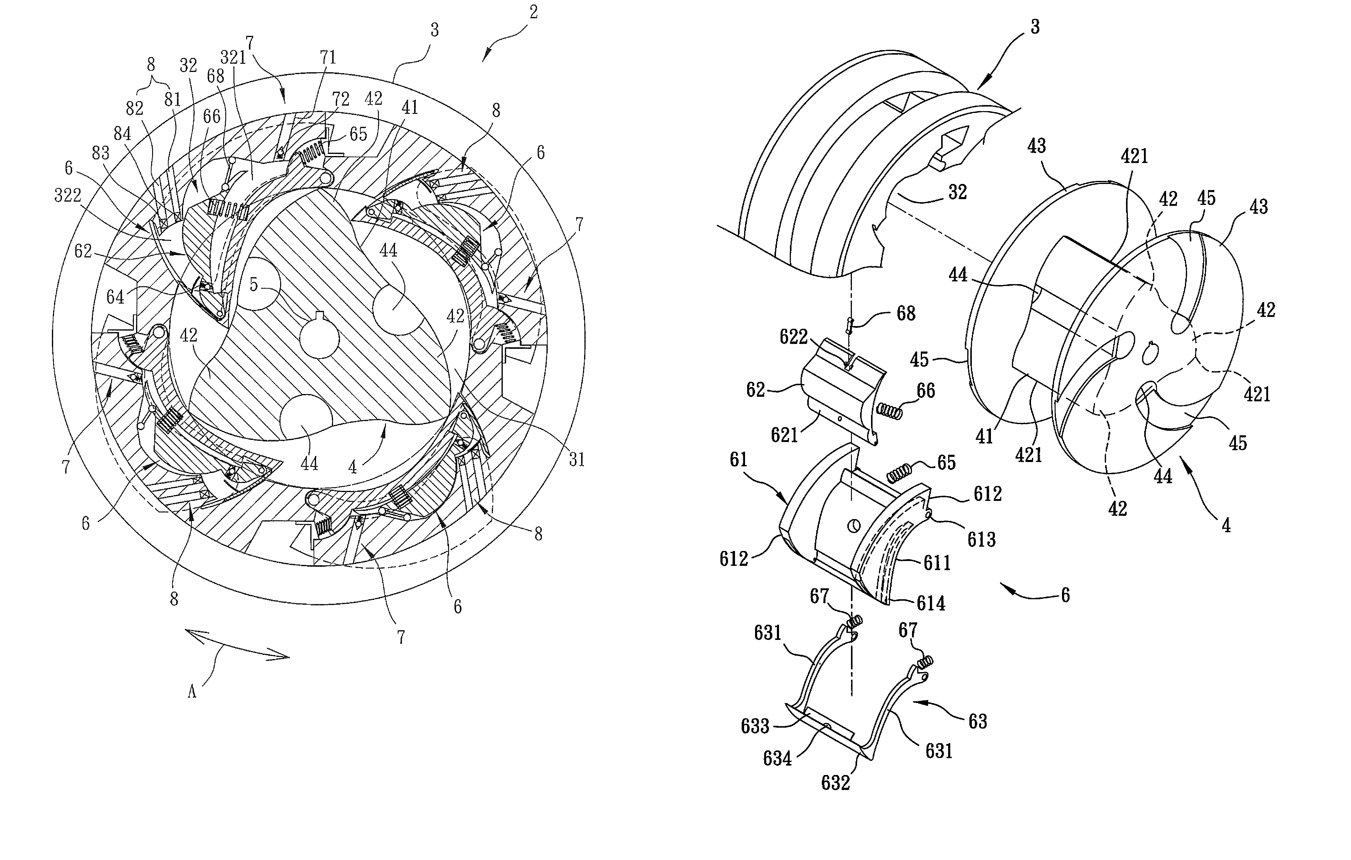
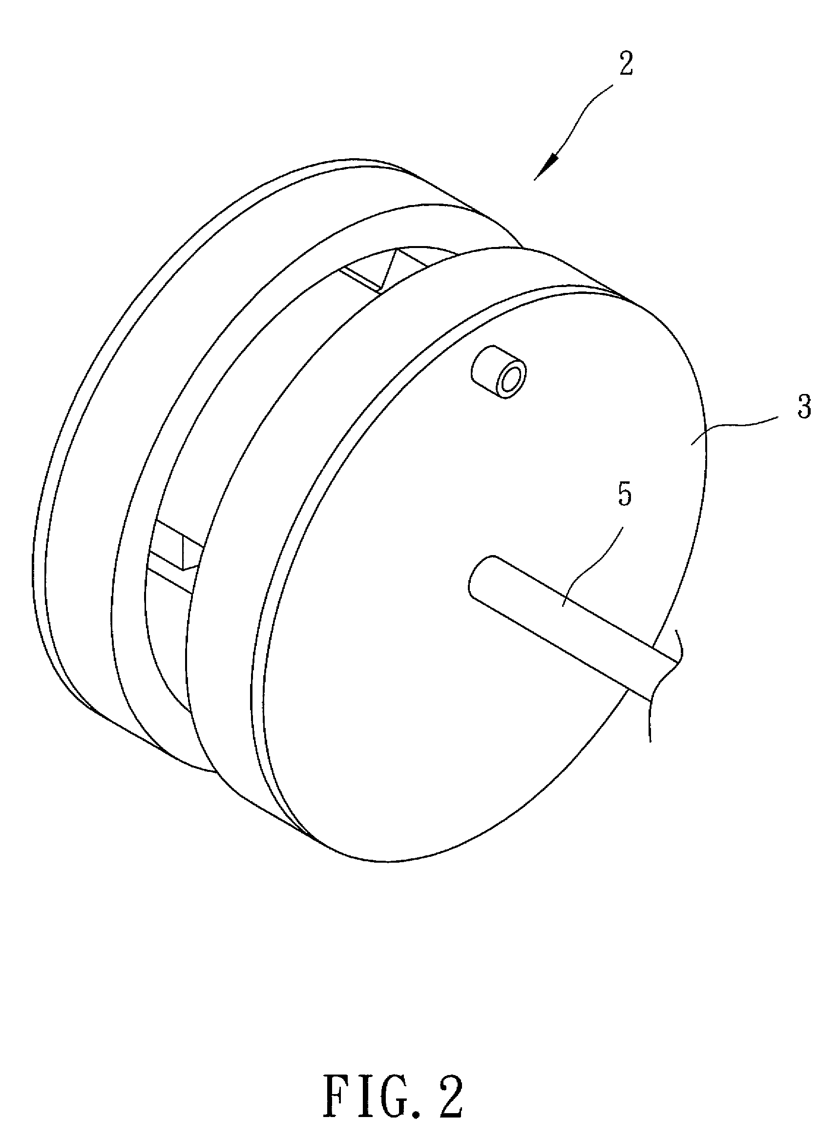
[0023]Referring to FIGS. 2 and 3, the preferred embodiment of a rotary engine 2 according to this invention includes an outer shell 3, a rotor 4, a power output shaft 5, four power-generating units 6, four intake units 7, and four ignition units 8.

[0024]With further reference to FIG. 4, the outer shell 3 has an accommodating space 31, two exhaust ports 33 in fluid communication with the accommodating space 31, and four working spaces 32 spaced apart from each other and arranged in a circumferential direction (A) (see FIG. 3) of the outer shell 3. The working spaces 32 are in fluid communication with the accommodating space 31.

[0025]With further reference to FIG. 5, the rotor 4 is disposed rotatably in the accommodating space 31, and includes a rotor body 41, three vanes 42 extending outwardly from the rotor body 41 and arranged in the circumferential direction (A), two side plates 43 disposed respectively and fixedly on two opposite sides of the rotor body 41 such that the vanes 42 ...


PUM


Abstract

A rotary engine includes an outer shell having a plurality of working spaces each receiving a power-generating unit. A rotor is rotatable within the outer shell, and includes a rotor body and a plurality of vanes. When the rotor rotates one revolution in the outer shell, each of the vanes drives each of the power-generating units to complete a working cycle including four strokes of intake, compression, combustion, and exhaust. In each combustion stroke, compressed gas is injected on the corresponding vane to rotate the rotor about the central axis of an output shaft.

Description

BACKGROUND OF THE INVENTION[0001]1. Field of the Invention[0002]This invention relates to an engine, and more particularly to a rotary engine that includes a plurality of vanes, which are rotatable by compressed gas injected thereon.[0003]2. Description of the Related Art[0004]Referring to FIG. 1, a conventional rotary engine 1 includes an outer shell 11, a rotor 12, an output shaft 13, and two spark plugs 14.[0005]The outer shell 11 includes a shell body 111 having an accommodating space 114, and a pair of intake and exhaust ports 112, 113 formed in the shell body 111 and in fluid communication with the accommodating space 114. The rotor 12 is rotatable within the accommodating space 114 in the outer shell 11, and has a generally triangular cross-section. The output shaft 13 extends into the shell body 111 of the outer shell 11 and the rotor 12, and is rotatable relative to the outer shell 11.[0006]When the rotor 12 rotates in the accommodating space 114, three gas chambers 115 are...

Claims


Application Information

Patent Timeline
Patent Type & Authority Patents(United States)
IPC IPC(8): F02B53/00F01C1/44F04C2/00F04C2/44F04C2/34F04C18/00
CPCF01C1/46F01C21/0809
Inventor WANG, SERN-BEAN
Owner WANG SERN BEAN
Why Eureka
Try Eureka