Method and apparatus for determining position and rotational orientation of an object

a technology of rotational orientation and position information, applied in the direction of process and machine control, instruments, electromagnetic radiation sensing, etc., can solve the problems of lack of positional determination, lack of method development, and inability to provide angular orientation information such as attitude, direction or heading, and achieve accurate determining of position and rotational orientation

Active Publication Date: 2010-12-07
SHENZHEN INVENTION DISCOVERY CO LTD
View PDF27 Cites 207 Cited by
  • Summary
  • Abstract
  • Description
  • Claims
  • Application Information

AI Technical Summary

Benefits of technology

[0021]The present invention provides a method and an apparatus for accurately determining position and rotational orientation within a predefined space, such as a designated area or volume inside a building. The present invention can be employed to determine location in one or two dimensions and rotational orientation in one degree of freedom. It can be applied to stationary and / or mobile objects and can measure the objects position and orientation in real-time as it moves freely within the designated area.
[0029]In a preferred embodiment, the processing step c) selects the position marker offering best image clarity and “readability”, and uses the selected position marker for the calculation of step d). Alternatively, more than one position marker may be selected, and the position and rotational orientation of the object may be calculated for each selected position marker to verify the calculation and improve the precision of the position and rotational orientation determination.

Problems solved by technology

Many technologies have been applied to position determination in one, two, and three dimensions, including optical, ultrasonic, and radio, but most methods do not provide angular orientation information such as attitude, direction, or heading.
Other methods have been developed for angular measurement, but may lack positional determination.
For example, Global Positioning System (GPS) is a widely recognized position determination technology, but it lacks orientation determination capability for stationary objects.
GPS operability suffers indoors from signal attenuation and reflections, so it is not a good choice for indoor applications.
Ultrasonic methods that operate well indoors have been designed to replicate GPS' capability, but they, too, lack orientation determination.
The system allows low cost sensors to be used, but requires active markers, such that upon loss of power, the markers become undetectable by the sensor.
Said targets are adhered to surrounding walls of the operation area, but they may become obscured in a factory or warehouse where stacks of materials may block the line of sight between detector and target.
Inertial methods can provide orientation detection, but do not provide accuracy obtainable by other methods and are subject to drift through time.
Complexity and cost are drawbacks to implementing this method.

Method used


Image

  • Method and apparatus for determining position and rotational orientation of an object
  • Method and apparatus for determining position and rotational orientation of an object
  • Method and apparatus for determining position and rotational orientation of an object

Examples


second embodiment

Description of the Second Embodiment

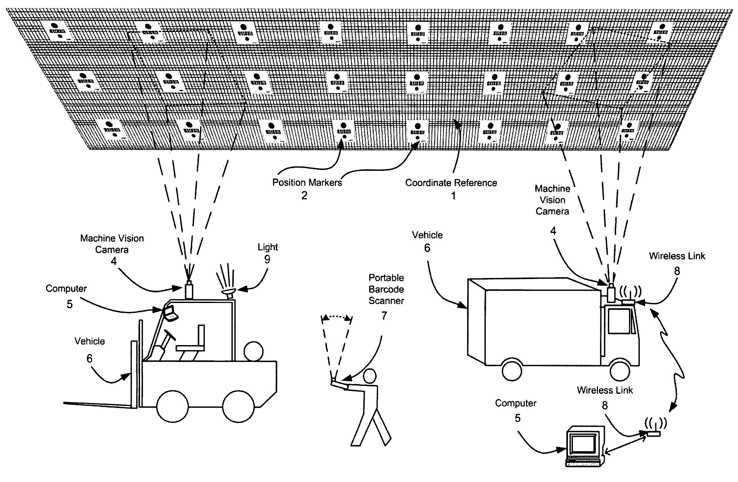
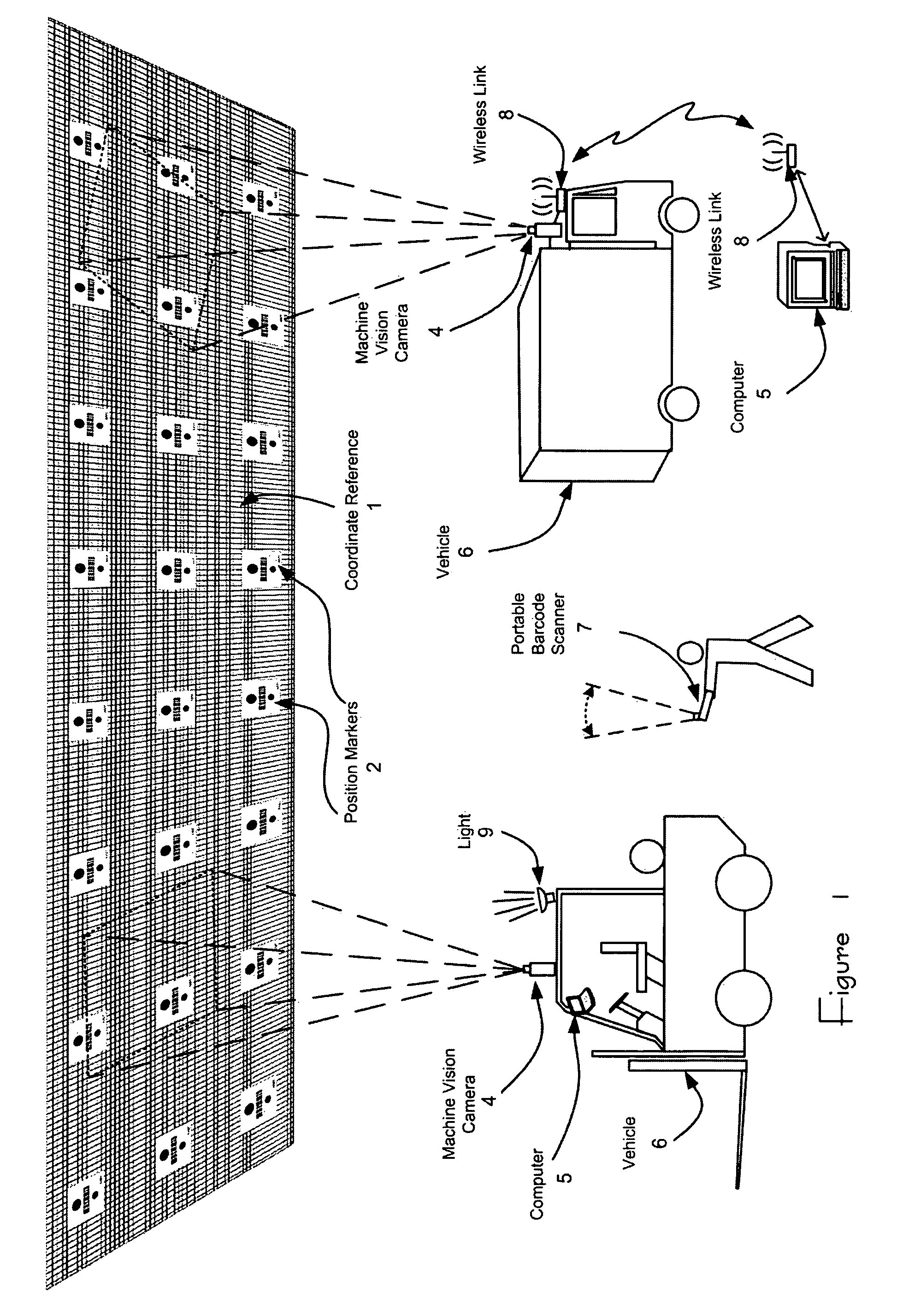
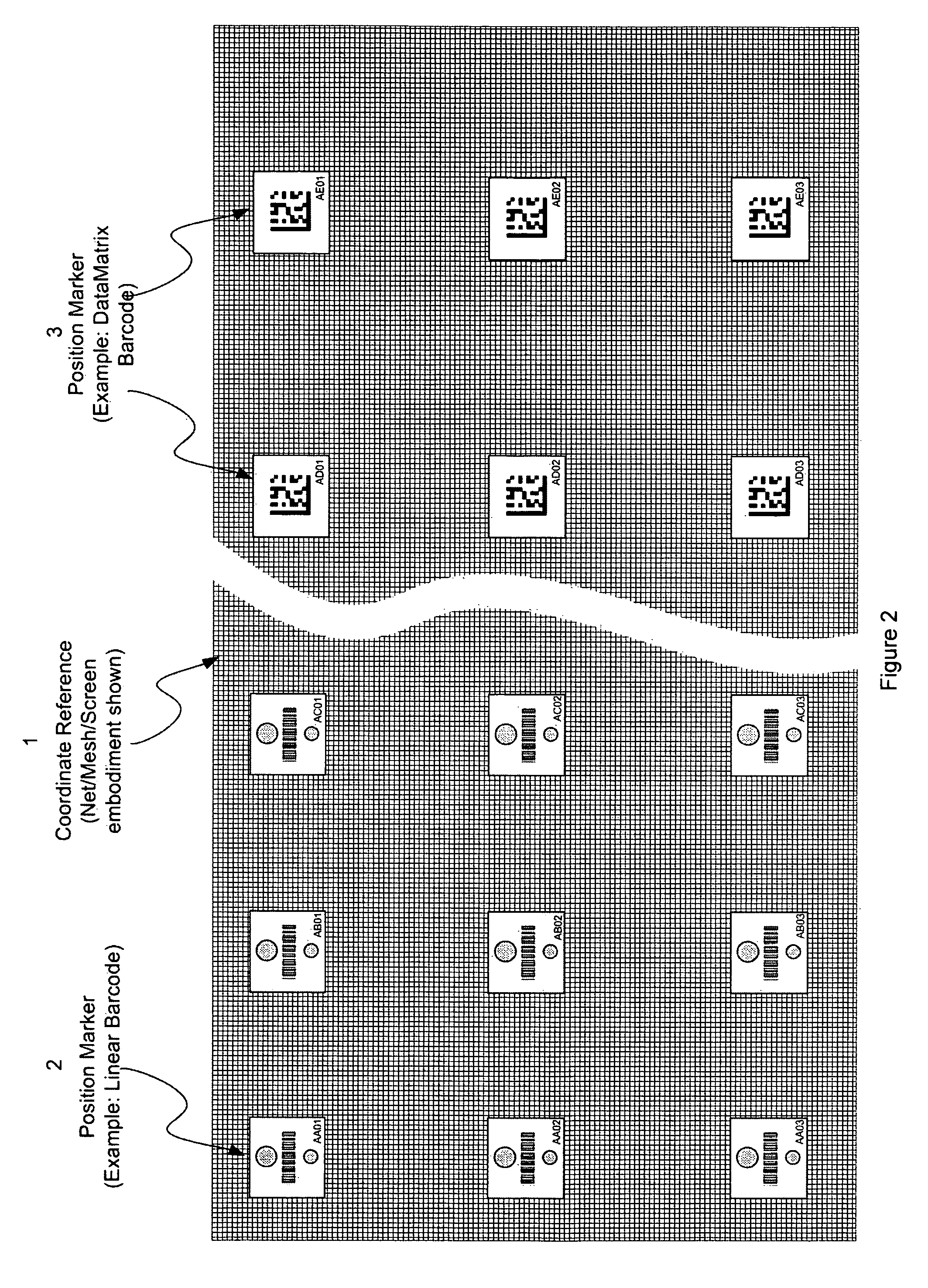
[0095]Referring to FIGS. 1 and 2, a second embodiment will now be described. Steps omitted are assumed to be unchanged from the preferred embodiment. This embodiment utilizes two-dimensional bar codes. Coordinate reference 1 consists of position markers 3 (FIG. 12), which are fabricated of labels 3b and substrates 3a. Bar code symbols, each containing a unique identification encoded in two-dimensional bar code symbology are printed on the label stock, along with human readable text. Bar codes of standard formats can be used including DataMatrix, Code One, PDF417, Array Tag, and QR Code. DataMatrix symbols are chosen in this embodiment for their ubiquitous usage, error correction robustness, and well developed suite of image processing software available in commercial machine vision systems.

Image Capture and Marker Identification (100, 110, 120, 130, and 300)

[0096]Referring to FIGS. 1, 8, 17, 18, and 19, the following steps take place. The machine ...

third embodiment

Description of the Third Embodiment

[0101]The invention can operate in a second physical arrangement wherein the camera is fixed in space and the markers are affixed to movable objects. FIG. 20 presents an application example, where machine vision camera 4 is mounted overhead and a position marker 2 or 3 is affixed to a vehicle. The camera views a predetermined area as vehicle 6 moves about the area. The marker is within the field of view so long as the vehicle remains within the predetermined area. Image processing steps are identical to embodiment 1 and 2, with the exception that camera coordinates in real space are used as a reference point, and object coordinates are calculated from image data. Image analysis steps are identical to earlier examples, but the transformation of image data into of position data differs; in this arrangement the system determines where a viewed object is located instead of determining where the system itself is located. Orientation is calculated direct...


PUM


Abstract

A method and apparatus for determining position and rotational orientation of an object within a predetermined area is disclosed. Position markers, encoded with their identity, are viewed with a camera, images are captured and processed, and the position and rotational orientation of the object are calculated. Three embodiments are disclosed; the first having a camera mounted on the movable object while position markers bearing linear bar codes are fixed in location, the second having a camera mounted on the movable object while position markers bearing two-dimensional bar codes are fixed in location, and the third having a position marker of either type affixed to the object while the camera is fixed in location.

Description

PRIORITY CLAIM[0001]This application claims the benefit of U.S. Provisional Application 60 / 635,813, filed 14 Dec. 2004.SCOPE OF THE INVENTION[0002]The invention presents a method, apparatus, and system for determining position and rotational orientation of an object in a predefined two-dimensional space.FIELD OF THE INVENTION[0003]A method, apparatus, and system to determine the position and rotational orientation of an object in a predefined space, in which a machine vision image acquisition apparatus acquires an image and processes the acquired image, and a computer calculates the object's position and rotational orientation based on processed image data. Position is determined in one or two dimensions. Rotational orientation (heading) is determined in the degree of freedom parallel to the plane of motion.[0004]The method and apparatus of the present invention present a general solution to the problem of object location and may be applied to many fields of use. Two application exa...

Claims


Application Information

Patent Timeline
Patent Type & Authority Patents(United States)
IPC IPC(8): G06K7/10
CPCG01S5/16G05D1/0234B66F9/24B66F9/0755G05D2201/0216
Inventor EMANUEL, DAVID C.MAHAN, LARRY G.UNGERBUEHLER, RICHARD H.
Owner SHENZHEN INVENTION DISCOVERY CO LTD
Why Eureka
Try Eureka