
Igniter assembly

a technology of igniter and assembly, which is applied in the direction of electric fuzes, pedestrian/occupant safety arrangements, vehicular safety arrangements, etc., can solve the problems of reducing the space for inserting injection molds into the collars, difficult formation of gaps, and unable to flow smoothly into the molds

Active Publication Date: 2010-12-21
DAICEL CHEM IND LTD
View PDF7 Cites 10 Cited by
  • Summary
  • Abstract
  • Description
  • Claims
  • Application Information

AI Technical Summary

Benefits of technology

This configuration ensures reliable igniter fixation and improved sealing, preventing igniter dislodgment under pressure and facilitating uniform resin distribution for enhanced assembly quality and performance.

Problems solved by technology

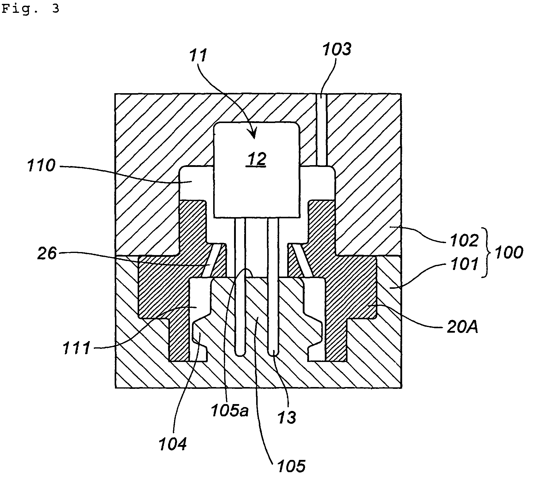
However, if the thickness of the inward flange portion is increased, the space for inserting an injection mold into the collar is decreased and, for example, a gap is difficult to form between the collar and the injection molding mold located below the collar and the resin can hardly flow smoothly into the mold.
In particular, in the case where only one resin injection port is provided (for example, only above the collar) to simplify the injection apparatus, the gap formed between the collar and mold is decreased, thereby impeding the flow of resin into the zone below the collar.

Method used


Image

  • Igniter assembly
  • Igniter assembly
  • Igniter assembly

Examples


Embodiment Construction

[0045]The present invention is to provide an igniter assembly in which an electric igniter is easily fixed into an igniter collar by resin, and a method for manufacturing the igniter assembly.

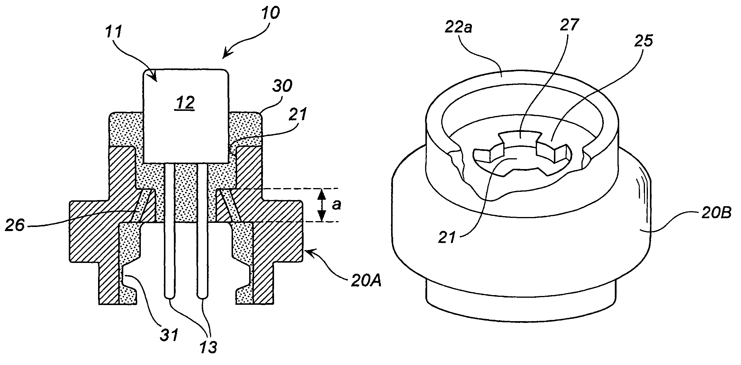
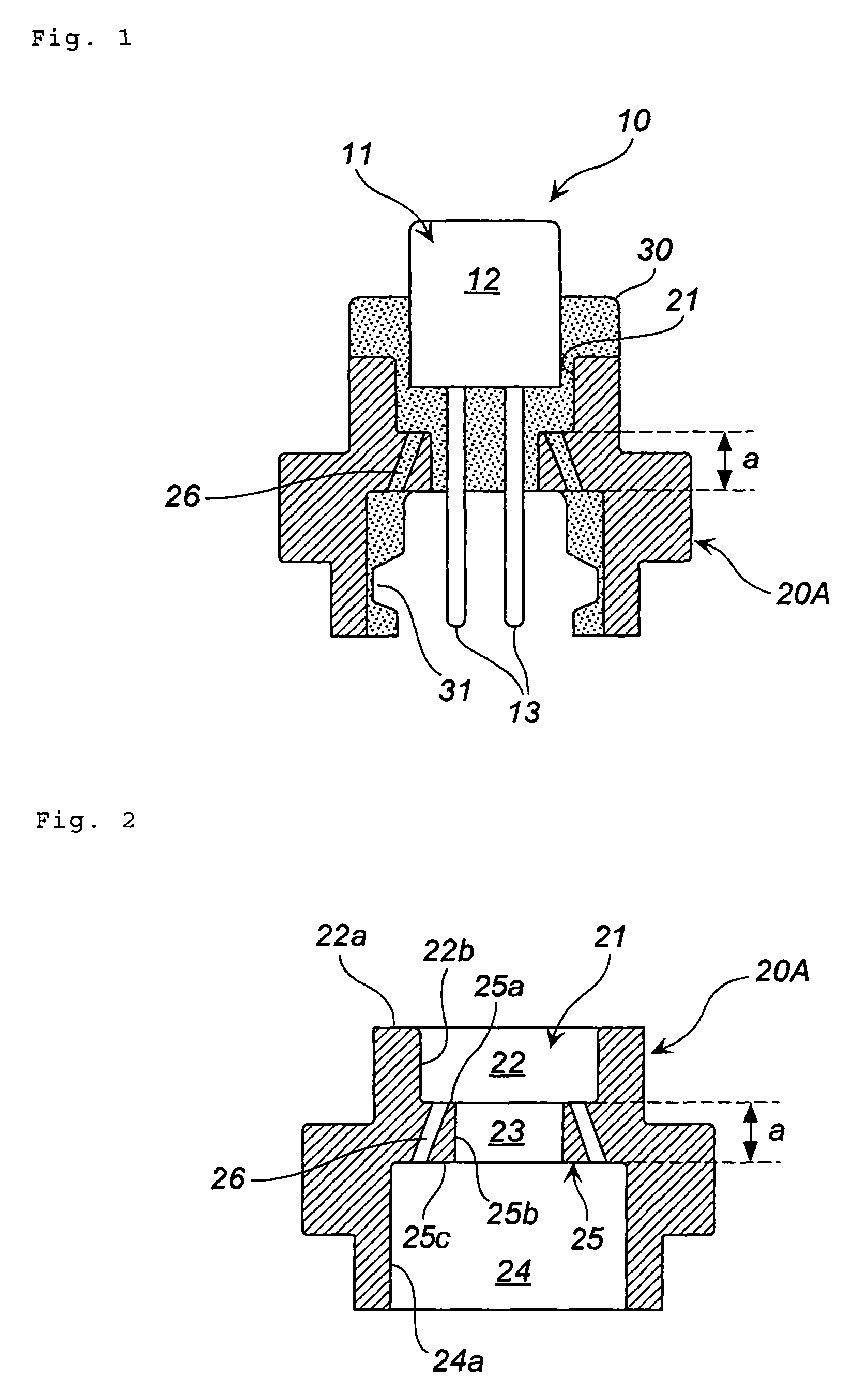
[0046]The igniter (electric igniter) is used as an initiation means of a passenger restraining device for an automobile, such as a gas generator for an airbag, and includes an igniter main body (includes an ignition agent, a bridge wire for igniting the ignition agent, a thin-film bridge, and a heat source such as a nichrome wire) and a conductive pin for supplying electric energy to the igniter main body, and is installed in a state of being fixed inside a metallic igniter collar with a resin.

[0047]When the igniter is fixed to the igniter collar, a method is employed including the steps of placing the igniter and igniter collar in a mold (combination of an upper mold and a lower mold), injecting a resin into the space formed between the metallic collar and igniter main body, and demolding.

[004...


PUM


Abstract

An igniter assembly includes, an electric igniter and igniter collar, and a resin fixing the electric igniter into the igniter collar. The electric igniter has an igniter main body and a conductive pin which extends from the igniter main body. The igniter collar has a first through hole formed in the axial direction and at least one second through hole formed separately from the first through hole and being provided to the igniter collar. The electric igniter is fixed inside the first through hole by the resin, and the resin is also charged into the second through hole.

Description

[0001]This nonprovisional application claims priority under 35 U.S.C. §119(a) on Patent Application No. 2005-323132 filed in Japan on 8 Nov. 2005, and 35 U.S.C. §119(e) on U.S. Provisional Application No. 60 / 73,5848 filed on 14 Nov. 2005, which are incorporated by reference.BACKGROUND OF THE INVENTION[0002]1. Field of Invention[0003]The present invention relates to an igniter assembly for use in a gas generator and to an assembling method therefor.[0004]2. Description of Related Art[0005]Because of an advantage in cost thereof, a structure in which an igniter main body is integrated with an igniter collar by a resin is presently widely used in igniter assemblies. A resin or the like is used for integration and the assembling is performed by an injection molding method.[0006]JP-A No. 11-321541 (U.S. Pat. No. 6,073,963) discloses an igniter assembly for use in a gas generator for an air bag. When an injection molding method is employed to assemble the igniter assembly, a molding die i...

Claims


Application Information

Patent Timeline
Patent Type & Authority Patents(United States)
IPC IPC(8): F42B3/10
CPCF42B3/103F42B3/195B60R2021/26029
Inventor ODA, SHINGO
Owner DAICEL CHEM IND LTD
Learn More