Discharge lamp ballast and projector

a technology of discharge lamp and discharge lamp, which is applied in the direction of electric variable regulation, process and machine control, instruments, etc., can solve the problems of difficulty in seeing screen image, easy to occur the phenomenon of arc origin point jumping to other points,

Inactive Publication Date: 2007-07-19
MATSUSHITA ELECTRIC WORKS LTD
View PDF23 Cites 46 Cited by
  • Summary
  • Abstract
  • Description
  • Claims
  • Application Information

AI Technical Summary

Benefits of technology

[0032] Preferably, the projector comprises a color filter whose transmission color by light from the light source is timewise changed with a prescribed period, and the control circuit synchronizes timing of polarity inversion of lamp voltage applied across the lamp with timing that the transmission color of the color filter is changed. According to this configuration, in case that color image is displayed by timewis

Problems solved by technology

However, if the arc length is shortened, an arc generation point on an electrode gets unstable depending on temperature or surface condition of the electrode, so that the phenomenon that the arc origin point jumps to other points is easy to occur.
When this sort of phenomenon occurs, visible flicker is perceived in light output of the lamp, and in case that the lamp is utilized as a light source for a projector, problems are raised, such as difficulty seeing screen image due to brightness fluctuation or luminance reduction on pla

Method used


Image

  • Discharge lamp ballast and projector
  • Discharge lamp ballast and projector
  • Discharge lamp ballast and projector

Examples


first embodiment

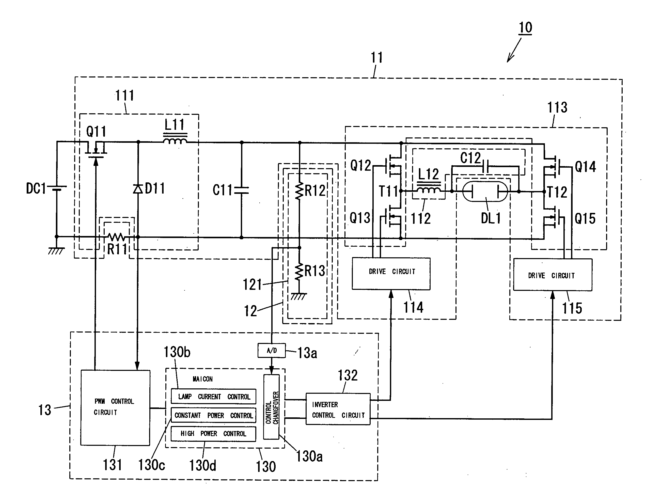
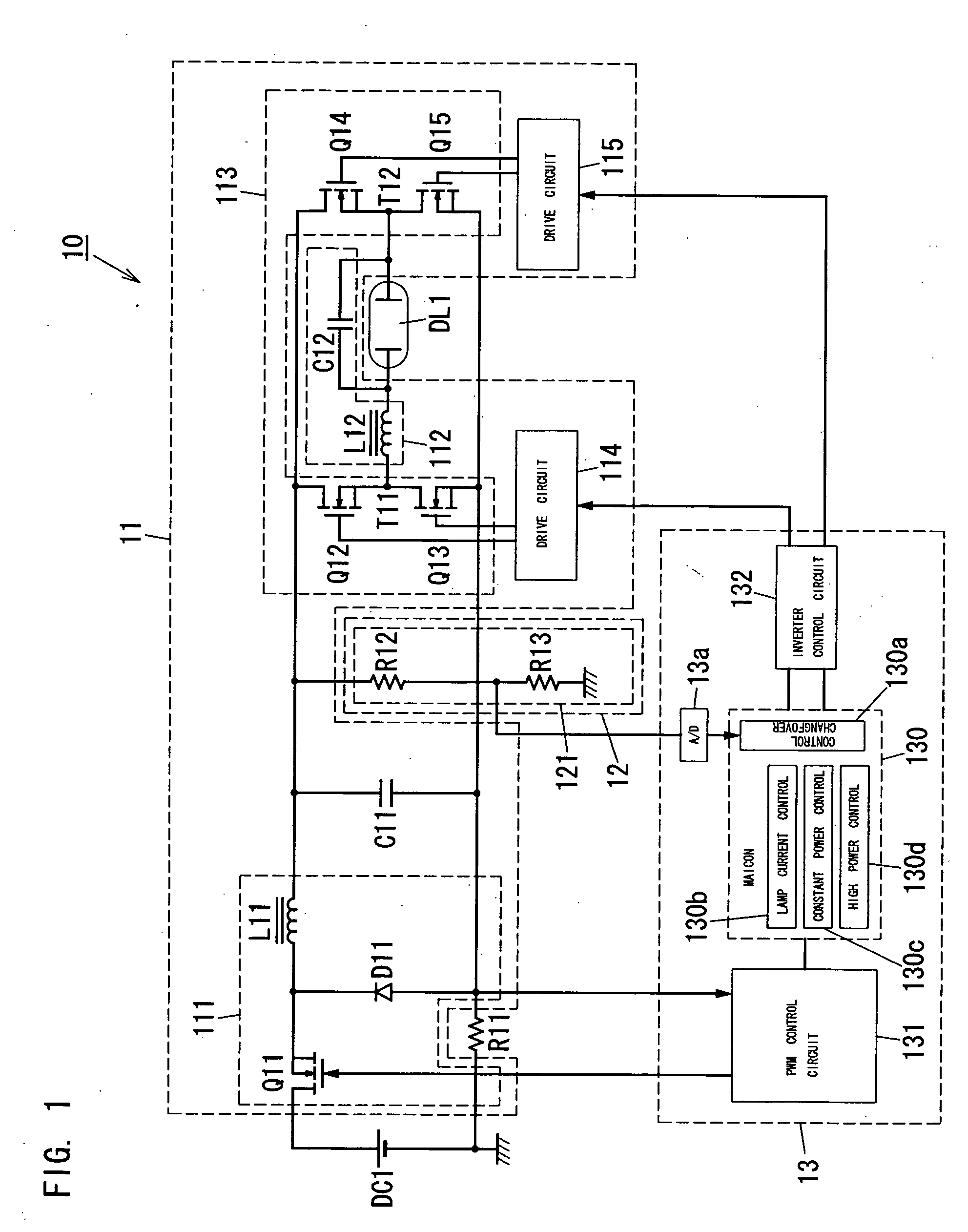
[0059]FIG. 1 shows a discharge lamp ballast 10 for a HID lamp (e.g., extra-high-pressure mercury discharge lamp of 120-300 W) DL1. The ballast 10 comprises a resistor R11 for detecting an input current, a state detection circuit 12, a control circuit 13 and an igniter (not shown), and further comprises a power converter 11 connected between a DC power source DC1 with a positive terminal and a negative terminal and a HID lamp DL1 with a first terminal and a second terminal. In order to start the lamp DL1, the igniter generates and applies high voltage to the lamp DL1.

[0060] The power converter 11 comprises a DC-DC converter 111, a low pass filter 112, an inverter 113 with output terminals T11 and T12, and drive circuits 114 and 115, and further comprises a capacitor (smooth condenser) C11 that provides DC power from the DC-DC converter 111 for the lamp DL1.

[0061] The DC-DC converter 111 can be constructed of, for example, a voltage step down converter having a diode D11, a switchin...

second embodiment

[0089]FIG. 7 shows a discharge lamp ballast 20 for a HID lamp (e.g., extra-high-pressure mercury discharge lamp of 120-300 W) DL2. The ballast 20 is characterized by a state detection circuit 22 and a control circuit 23, and different from the first embodiment that the state detection circuit 12 is constructed of the voltage division circuit 121 and the control circuit 13 is constructed of the A / D converter 13a, the micon 130, the PWM control circuit 131 and the inverter control circuit 132.

[0090] In this second embodiment, the state detection circuit 22 comprises a voltage division circuit 221 similar to the voltage division circuit 121, and also comprises a resistor R24 with small resistance, a current detection circuit 222 and a light output detection circuit 223.

[0091] The resistor R24 is connected between a negative voltage side of a capacitor C21 (negative terminal) and sources of switching elements Q23 and Q25, and detects voltage corresponding to a lamp current through the...

third embodiment

[0108]FIG. 14 shows a discharge lamp ballast 30 for a HID lamp (e.g., extra-high-pressure mercury discharge lamp of 120-300 W) DL3. The ballast 30 is characterized by a control circuit 33, and different from the first embodiment that the control circuit 13 is constructed of the A / D converter 13a, the micon 130, the PWM control circuit 131 and the inverter control circuit 132.

[0109] In this third embodiment, the control circuit 33 comprises a micon 330 and an integration circuit 333 in addition to an A / D converter 33a, a PWM control circuit 331 and an inverter control circuit 332.

[0110] The micon 330 is characterized by a high power control function 330d with a non-correction control function 330H and a correction control function 330E, and a control changeover function 330a in comparison with the micon 130 of the first embodiment.

[0111] The non-correction control function 330H is operable to control the on / off state of the switching element Q31 so that a part of lamp power provid...


PUM


Abstract

A DC-DC converter 111 with a switching element Q11 changes a supply of power to a HID lamp DL1. On/off of the element Q11 is controlled with a control circuit 13. The circuit 13 controls an on/off state of the element Q11 with constant lamp power control on stable operation of the lamp. The circuit 13 controls the on/off state of the element Q11 so as to provide the lamp with lamp power larger than lamp power by the constant lamp power control based on high power control for a period of time that the lamp is on. It is possible to keep temperature of electrodes and within a bulb of the lamp in a proper state through simple control, and to prevent flicker generation and electrode degradation.

Description

TECHNICAL FIELD [0001] The invention relates to discharge lamp ballasts utilized for operating high intensity discharge lamps (HID lamps), and projectors equipped with the discharge lamp ballasts. BACKGROUND ART [0002] In conventional discharge lamp ballasts, HID lamps are operated by, for example, square wave voltage. In case of an extra high pressure mercury lamp utilized as a light source for a projector, square wave voltage with a comparatively low frequency (approx. 100s Hz) is applied across the lamp in order to prevent occurrence of acoustic resonance phenomenon (see, e.g., Japanese Patent Application Publication number 2002-352982). [0003] In these sorts of applications, arc length of the lamp is required to be as short as possible in order to approximate it to a point source. However, if the arc length is shortened, an arc generation point on an electrode gets unstable depending on temperature or surface condition of the electrode, so that the phenomenon that the arc origin...

Claims


Application Information

Patent Timeline
IPC IPC(8): H05B41/36H05B41/288
CPCH04N9/3114H04N9/3155H04N9/3182Y02B20/208H05B41/2882H05B41/2928H04N9/3197Y02B20/00
Inventor WATANABE, KOJIKONISHI, HIROFUMIHASEGAWA, JUNICHINAKADA, KATSUYOSHISASAKI, TOSHIAKI
Owner MATSUSHITA ELECTRIC WORKS LTD
Why Eureka
Try Eureka