Electrodeless discharge lamp lighting device, light bulb type electrodeless fluorescent lamp and discharge lamp lighting device
a technology of discharge lamp and lighting device, which is applied in the direction of electric variable regulation, process and machine control, instruments, etc., can solve the problems of lamp inadequacies, dimmable fluorescent lamps that have not yet developed, and difficult to implement dimmable fluorescent lamps
- Summary
- Abstract
- Description
- Claims
- Application Information
AI Technical Summary
Benefits of technology
Problems solved by technology
Method used
Image
Examples
embodiment 1
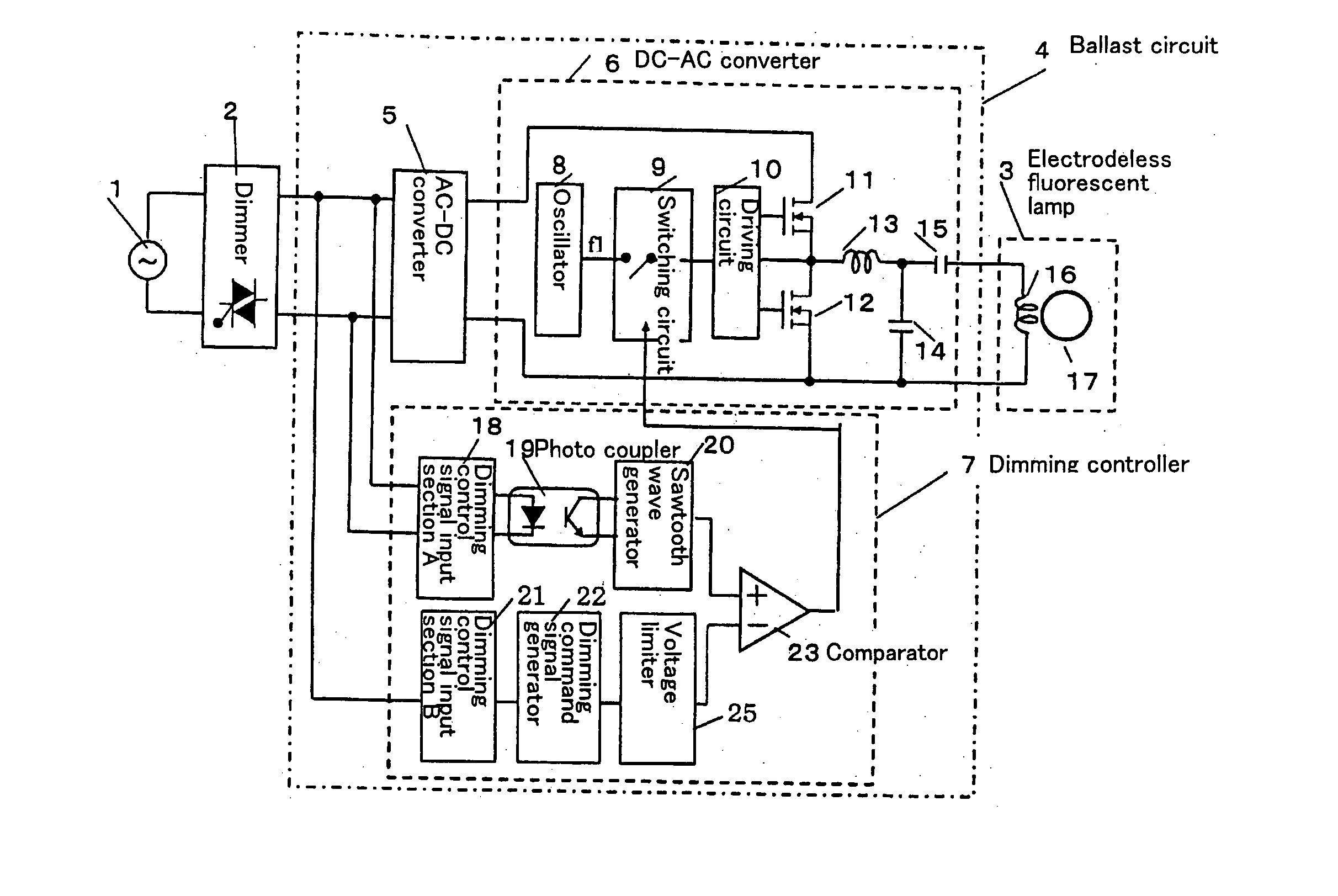
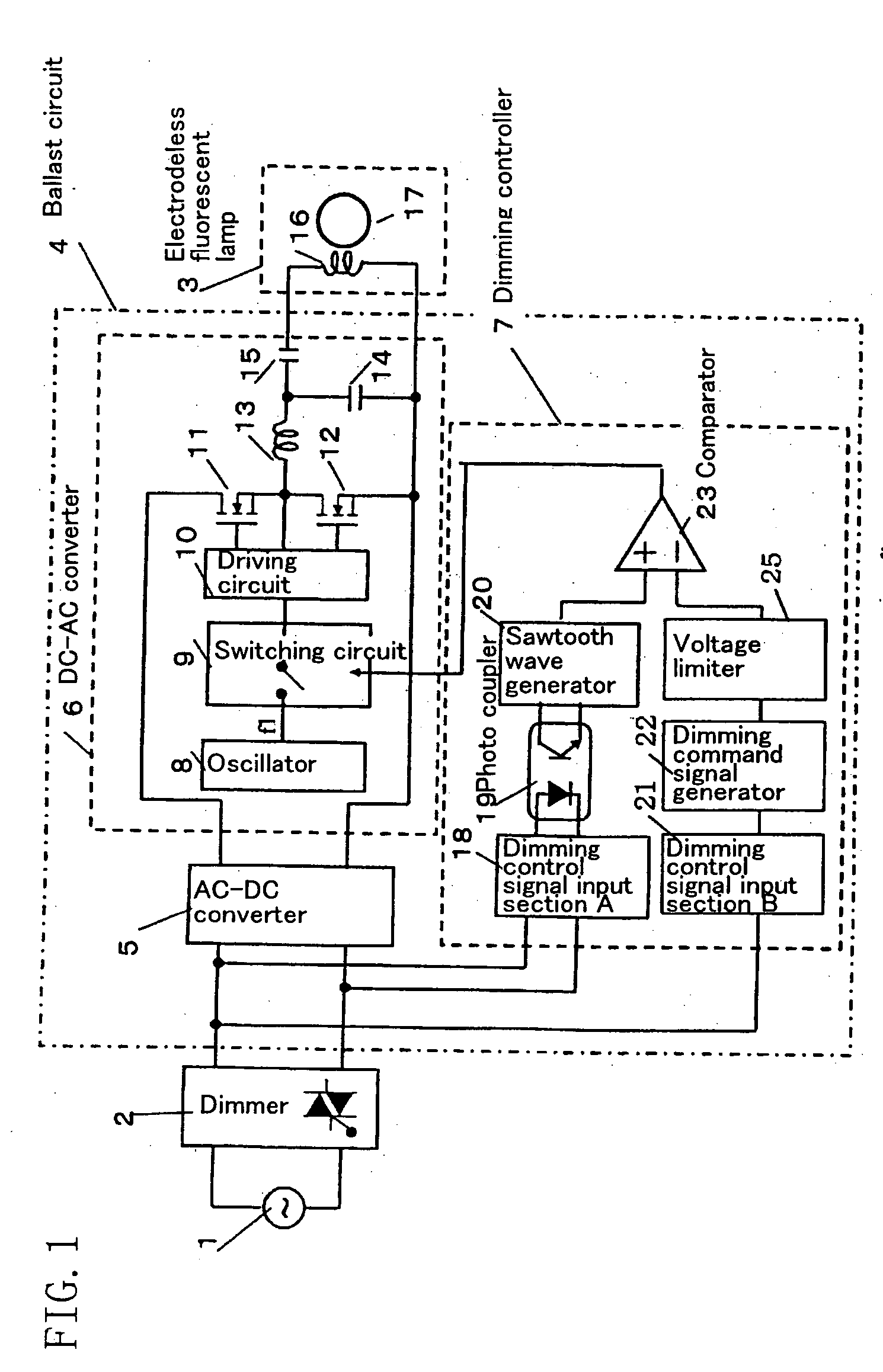
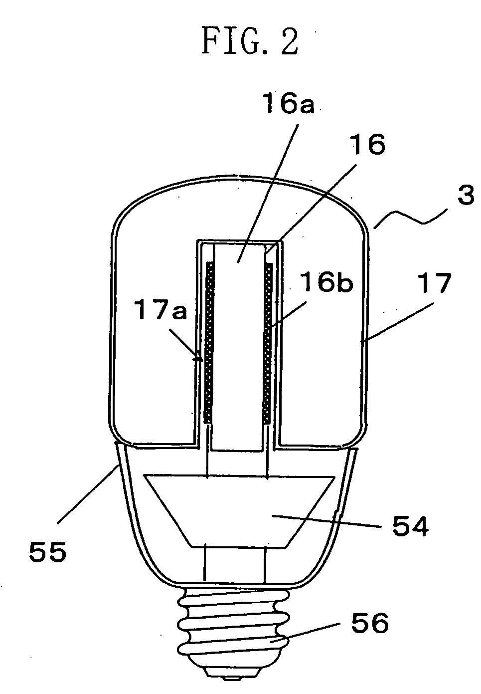
[0031]FIG. 1 schematically shows the configuration of a discharge lamp operating device (electrodeless discharge lamp operating device) according to a first embodiment of the present invention. And FIG. 2 is a cross-sectional view of the discharge lamp operating device of the present embodiment implemented as an electrodeless self-ballasted fluorescent lamp.
[0032] The electrodeless self-ballasted fluorescent lamp of the present embodiment includes: an electrodeless fluorescent lamp 3; a ballast circuit 4 (circuit board 54) for applying a high-frequency voltage to the electrodeless fluorescent lamp 3; and a lamp base 56 electrically connected to the ballast circuit 4 (circuit board 54). The circuit board 54 shown in FIG. 2 is formed with the ballast circuit 4 shown in FIG. 1. Specifically, the circuit board 54 is formed with wirings provided as shown in the ballast circuit 4, and is attached with respective circuit components.
[0033] As shown in FIG. 2, in the electrodeless self-bal...
embodiment 2
[0072] Hereinafter, a second embodiment of the present invention will be described with reference to FIG. 6. Although the configuration of a discharge lamp operating device of the present embodiment is similar to that described in the first embodiment, a sawtooth wave generator 20 for detecting the turn-on of a phase-controlled voltage is formed differently from the counterpart in the first embodiment, and can be formed inexpensively without using any IC in the configuration of the present embodiment.
[0073]FIG. 6 shows a circuit for detecting the turn-on of a phase-controlled voltage in the present embodiment, and in particular shows the configuration of the sawtooth wave generator 20. It should be noted that the same constituting elements as the counterparts described in the first embodiment are identified by the same reference characters, and the further description thereof will be omitted.
[0074] The sawtooth wave generator 20 shown in FIG. 6 has: a differentiating circuit 201; ...
embodiment 3
[0079]FIG. 7 is a circuit diagram of a discharge lamp operating device according to a third embodiment of the present invention. The third embodiment differs from the above-described first embodiment in that a discharge bulb 17′ has electrodes, and that a load resonant circuit is differently formed for the operation of a fluorescent lamp 3′ having electrodes. It should be noted that the same constituting elements as the counterparts described in the first embodiment are identified by the same reference characters, and the further description thereof will be omitted.
[0080] In the configuration of the present embodiment, as shown in FIG. 7, an LC resonant circuit including: a fluorescent lamp 3′; a resonant inductor 13; a resonant capacitor 15; and a capacitor 14 for resonance and preheat is connected between a drain terminal and a source terminal of a MOSFET 12.
[0081] In the configuration of the present embodiment, if a high voltage is generated as a resonance voltage at both ends ...
PUM
 Abstract
Description
Claims
Application Information
 - R&D
- Intellectual Property
- Life Sciences
- Materials
- Tech Scout
- Unparalleled Data Quality
- Higher Quality Content
- 60% Fewer Hallucinations
Browse by: Latest US Patents, China's latest patents, Technical Efficacy Thesaurus, Application Domain, Technology Topic, Popular Technical Reports.
© 2025 PatSnap. All rights reserved.Legal|Privacy policy|Modern Slavery Act Transparency Statement|Sitemap|About US| Contact US: help@patsnap.com


