Tube pump

a tube pump and peristaltic tube technology, applied in the direction of positive displacement liquid engines, couplings, machines/engines, etc., can solve the problems of hardly improving discharge accuracy, unable to continuously discharge liquid, and sagging or displaced tubes, so as to reduce the manufacturing cost of tubes

Inactive Publication Date: 2010-12-21
NOIBERUKU
View PDF18 Cites 13 Cited by
  • Summary
  • Abstract
  • Description
  • Claims
  • Application Information

AI Technical Summary

Benefits of technology

[0021]When the two tubes are connected to one tube for discharging liquid, a discharge amount of the liquid jointed into the one tube from the two tubes can be kept approximately constant. Thus, pulsation of discharge liquid can be suppressed and liquid can be continuously discharged.
[0030]According to the another aspect of the invention, the tube with two branched intermediate sections can be provided simply by connecting the tube elements to the Y-shaped connectors. Thus, manufacturing cost of the tube can be reduced.

Problems solved by technology

However, since the tube is strongly squeezed in the roller-type tube pump, the tube is considerably sagged or displaced.
Consequently, discharge accuracy is hardly improved.
Thus, in the tube pump, liquid usually cannot be continuously discharged because of the structure of the tube pump.

Method used


Image

  • Tube pump
  • Tube pump
  • Tube pump

Examples


Embodiment Construction

)

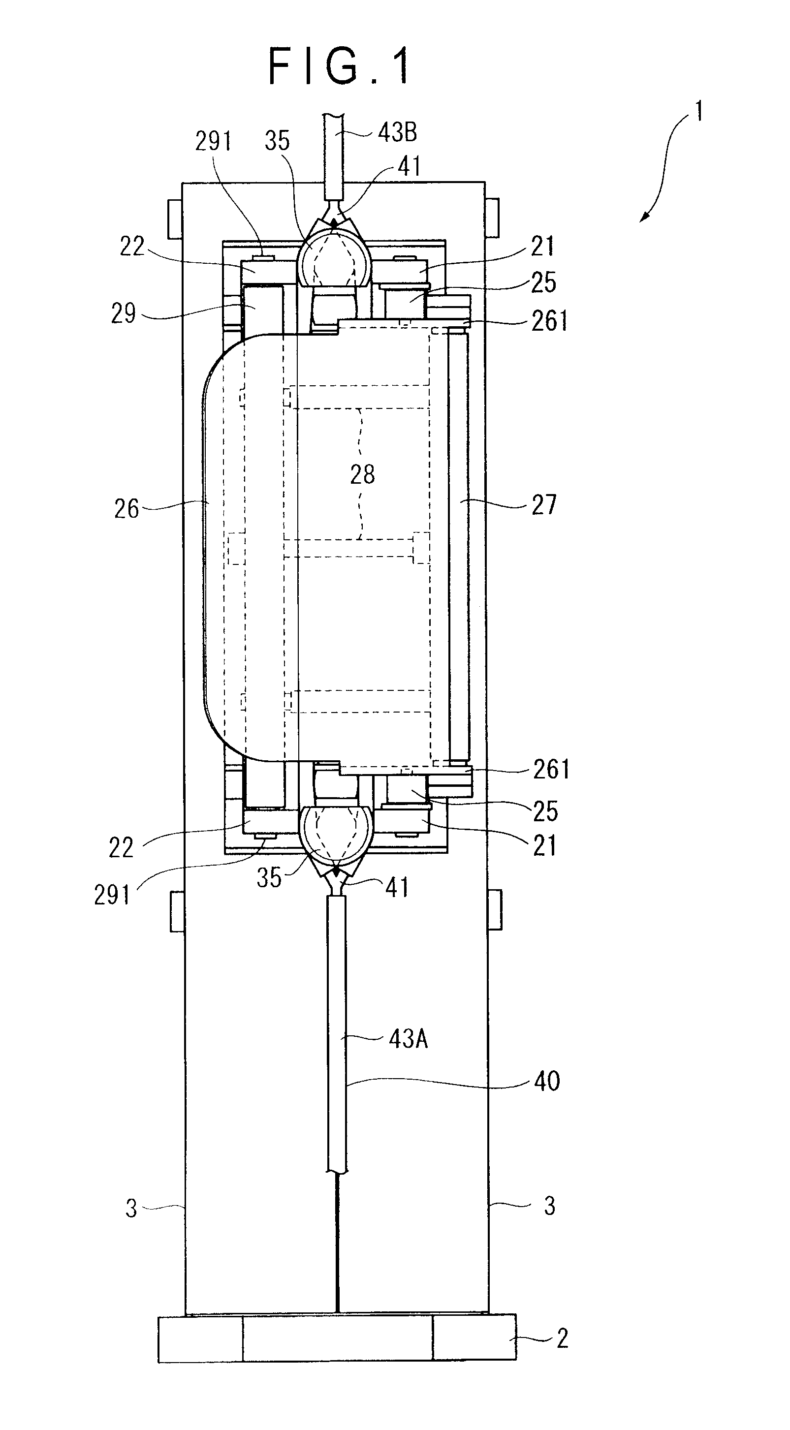
[0044]An arrangement of a tube pump according to an exemplary embodiment of the invention will be described below.

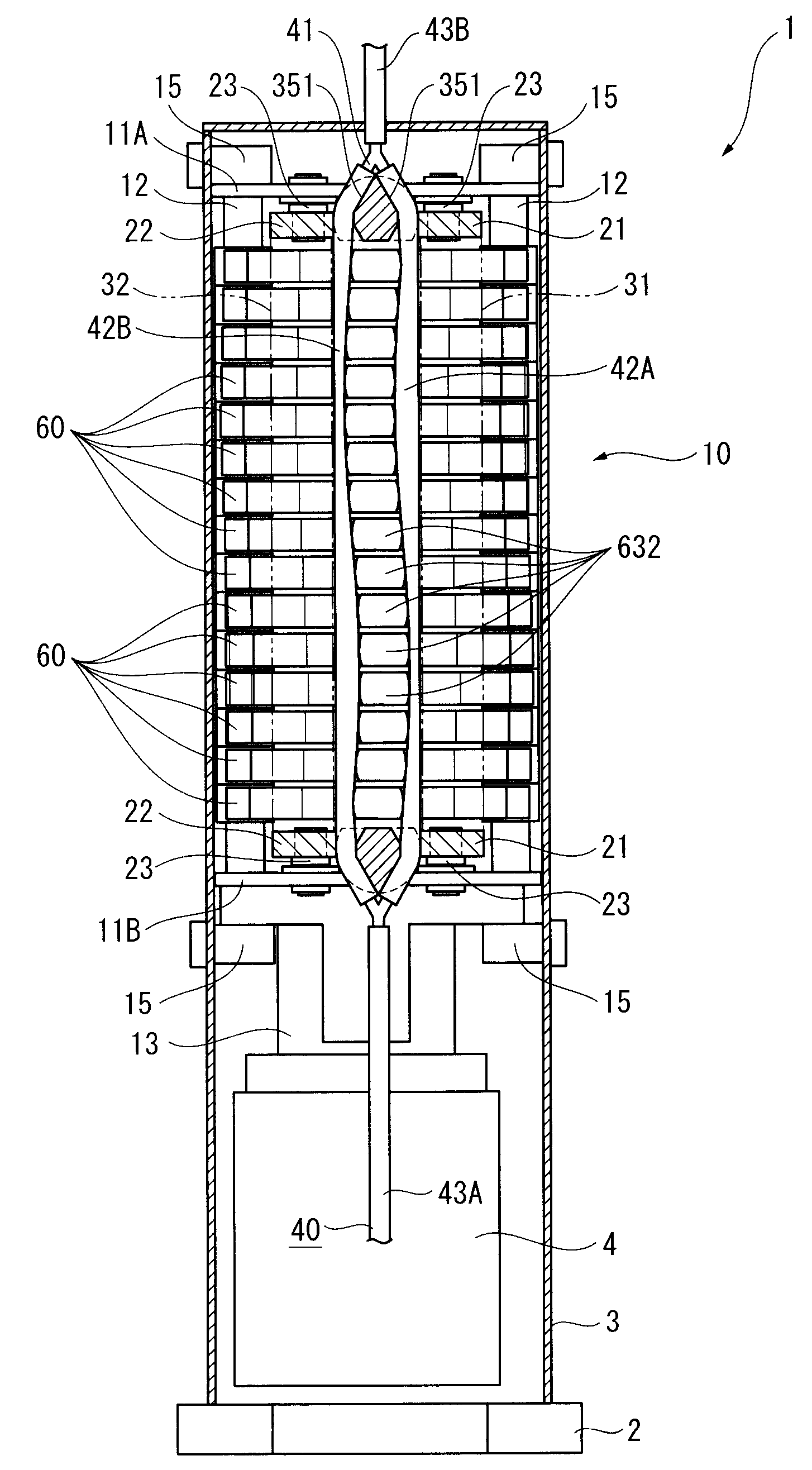
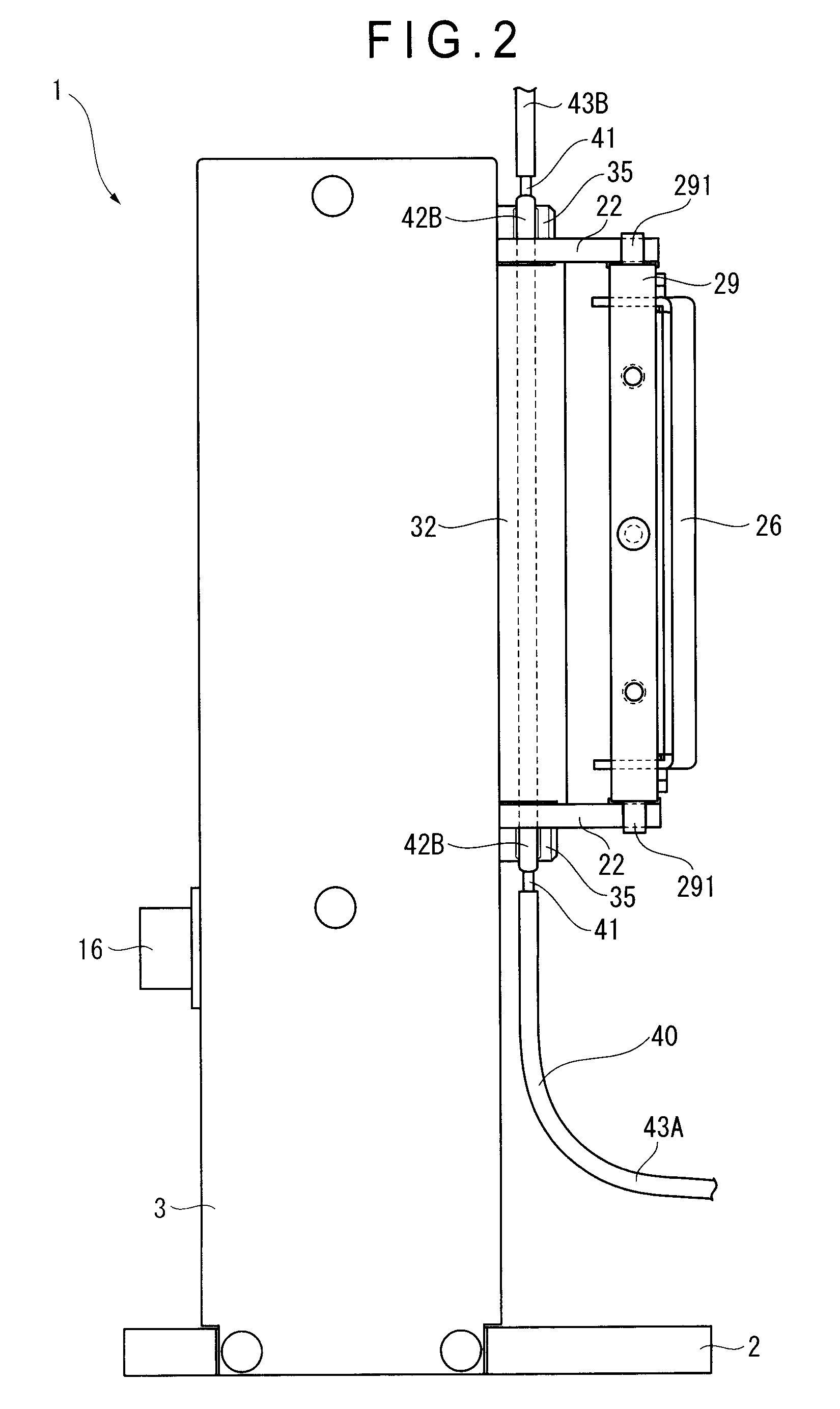
[0045]FIG. 1 is a front view of a finger-type tube pump 1 according to the exemplary embodiment. FIG. 2 is a side view of the tube pump 1 and FIG. 3 is a cross-sectional view of the tube pump 1.

[0046]The tube pump 1 includes a base 2 and a pair of covers 3 that are squared-C-shaped in horizontal cross section. A casing of the tube pump 1 is provided by the base 2 and covers 3.

[0047]As shown in FIGS. 4 and 5, a motor 4 and a pump assembly 10 are provided in the casing.

[0048]The pump assembly 10 includes a pair of planarly-rectangular side plates 11A and 11B that are vertically spaced away from each other. Four support shafts 12 are provided between the side plates 11A and 11B on four corners thereof. The side plates 11A and 11B are screwed to ends of the support shafts 12.

[0049]A motor flange 13 is attached to the side plate 11B provided on the lower side. The motor 4 is...


PUM


Abstract

A tube pump includes tubes, hooks, tube receivers, three or more fingers, and a drive mechanism. The tubes each include intermediate tubes, connectors, and end tubes. The tubes are attached by engaging the connectors with the hooks provided on upper and lower sides. The intermediate tubes are provided along the tube receivers. Tube press portions of the fingers are provided between the intermediate tubes. The fingers are driven by the drive mechanism so that the tube press portions are reciprocated between a position where one of the intermediate tubes is squeezed and a position where the other of the intermediate tubes is squeezed.

Description

[0001]The entire disclosure of Japanese Patent Application No. 2009-098189, filed Apr. 14, 2009, is expressly incorporated by reference herein.BACKGROUND OF THE INVENTION[0002]1. Field of the Invention[0003]The present invention relates to a peristaltic tube pump for discharging liquid by opening and closing spaces in a tube, and a tube used for the tube pump. More particularly, the present invention relates to a tube pump for continuously discharging a predetermined amount of liquid and a tube used for the tube pump.[0004]2. Description of Related Art[0005]In a typical tube pump, a flexible tube is squeezed by a roller, fingers or the like to sequentially change a position where the interior of the tube is opened and closed, so that liquid is sucked into, sequentially delivered through and discharged from the tube. The merit of such a tube pump is that the tube pump does not need to be sealed and therefore liquid is not accumulated in the tube pump.[0006]Thus, such a tube pump has ...

Claims


Application Information

Patent Timeline
Patent Type & Authority Patents(United States)
IPC IPC(8): F04B43/12
CPCF04B43/082F04B43/086F04B43/12Y10T137/9029
Inventor OGAWA, KENJI
Owner NOIBERUKU
Why Eureka
Try Eureka