
Inkjet printhead employing piezoelectric actuator and method of manufacturing the inkjet printhead

a piezoelectric actuator and inkjet printing technology, applied in printing and other directions, can solve the problems of difficulty in constant speed ejecting of ink droplets, irregular volume of ejecting ink droplets, etc., and achieve the effect of quick dampening a residual vibration of a piezoelectric layer

Inactive Publication Date: 2010-12-28
SAMSUNG ELECTRO MECHANICS CO LTD
View PDF11 Cites 3 Cited by
  • Summary
  • Abstract
  • Description
  • Claims
  • Application Information

AI Technical Summary

Benefits of technology

The damping layer significantly reduces residual vibration time by at least three times, enabling stable high-speed ink ejection, improved ejection response, and uniform ink droplet movement, resulting in high-quality printing with reduced cross-talk and enhanced durability.

Problems solved by technology

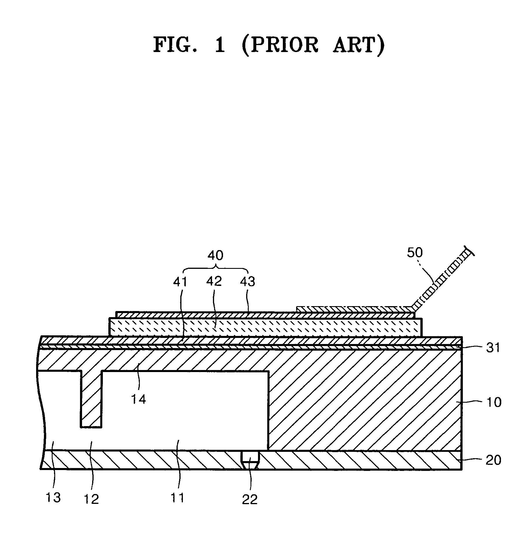
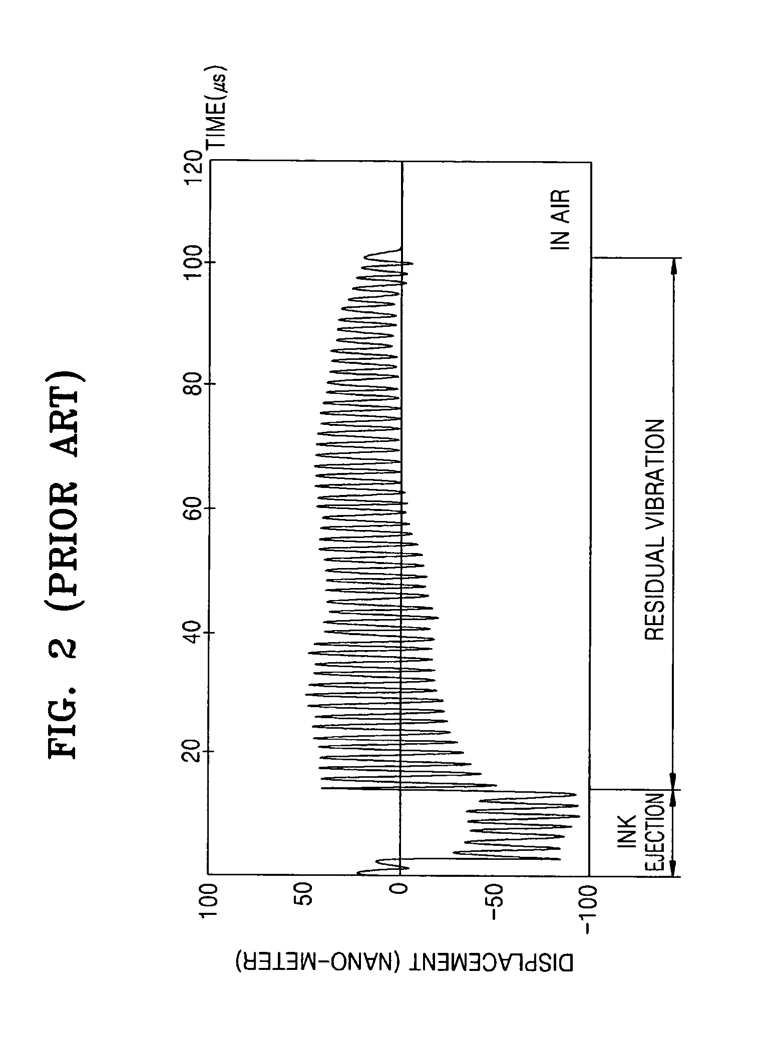
As a result, it is difficult to eject ink droplets at a constant speed and a volume of the ejected ink droplets may be irregular.

Method used


Image

  • Inkjet printhead employing piezoelectric actuator and method of manufacturing the inkjet printhead
  • Inkjet printhead employing piezoelectric actuator and method of manufacturing the inkjet printhead
  • Inkjet printhead employing piezoelectric actuator and method of manufacturing the inkjet printhead

Examples


Embodiment Construction

[0033]Reference will now be made in detail to the embodiments of the present general inventive concept, examples of which are illustrated in the accompanying drawings, wherein like reference numerals refer to the like elements throughout. The embodiments are described below in order to explain the present general inventive concept by referring to the figures. A size of each constituent element in the drawings may be exaggerated for a convenience of explanation. Also, where a layer is described to exist on another layer, the layer can exist while directly contacting the other layer or a third layer can exist therebetween.

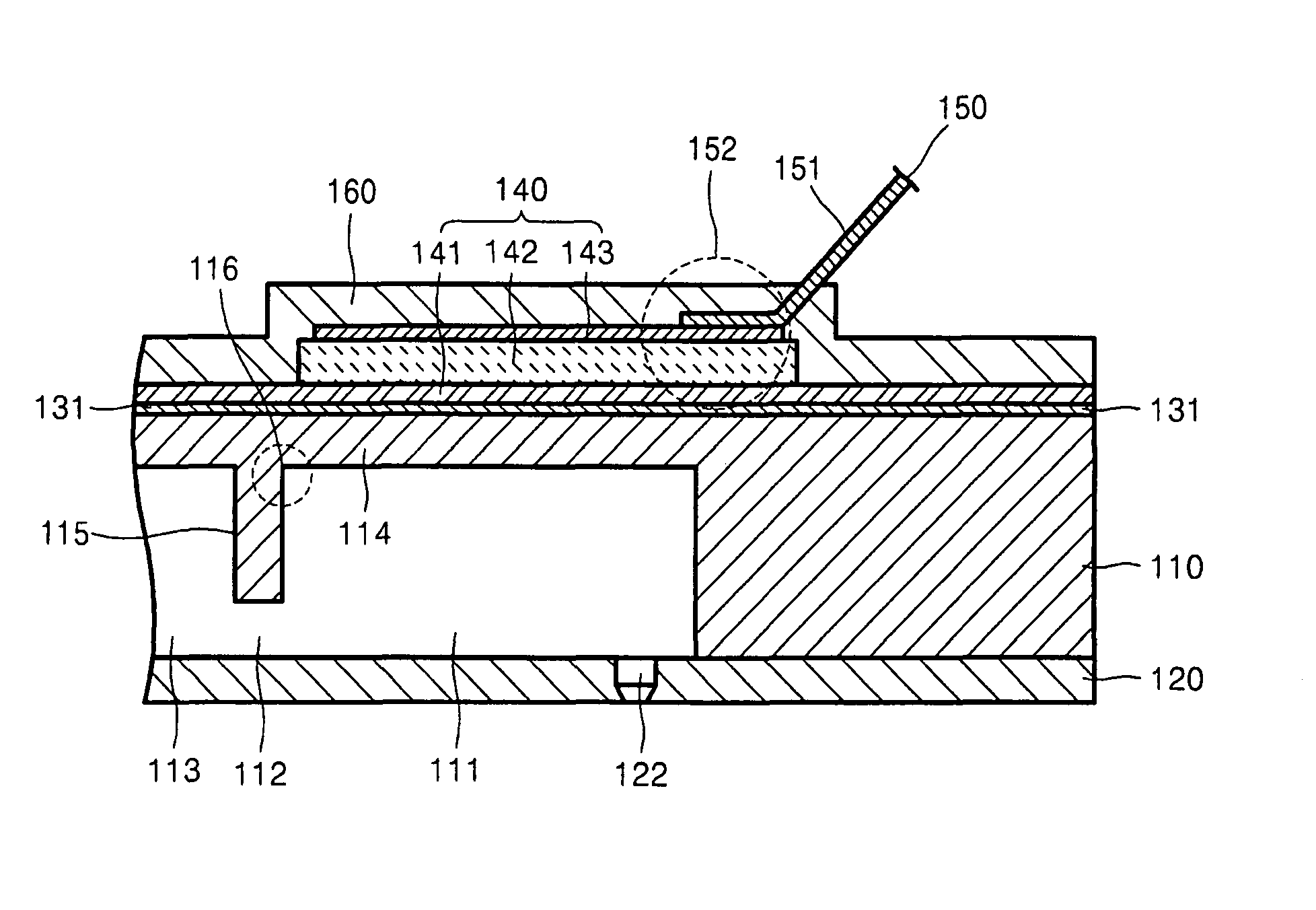
[0034]FIG. 3 is a cross-sectional view illustrating a configuration of an inkjet printhead, according to an embodiment of the present general inventive concept. FIG. 4 is a plan view illustrating the inkjet printhead of FIG. 3. Referring to FIGS. 3 and 4, an inkjet printhead according to an embodiment of the present general inventive concept includes a fluid path for...


PUM


Abstract

A piezoelectric inkjet printhead includes a fluid path forming substrate having a pressure chamber, a piezoelectric actuator formed on the fluid path forming substrate to provide a drive force to the pressure chamber to eject ink, and a damping layer formed on the piezoelectric actuator to dampen a residual vibration of the piezoelectric actuator.

Description

CROSS-REFERENCE TO RELATED APPLICATIONS[0001]This application claims priority under 35 U.S.C. §119(a) from Korean Patent Application No. 10-2006-0010055, filed on Feb. 2, 2006, in the Korean Intellectual Property Office, the disclosure of which is incorporated herein in its entirety by reference.BACKGROUND OF THE INVENTION[0002]1. Field of the Invention[0003]The present general inventive concept relates to an inkjet printhead, and more particularly, to an inkjet printhead to eject ink using a piezoelectric method, and a method of manufacturing the inkjet printhead.[0004]2. Description of the Related Art[0005]In general, an inkjet printhead prints a predetermined color image by ejecting fine droplets of printing ink to a desired position on a print paper. The inkjet printhead can be classified into two types according to an ink ejection method: a thermal inkjet printhead and a piezoelectric inkjet printhead. The thermal inkjet printhead generates a bubble in ink using a heat source t...

Claims


Application Information

Patent Timeline
Patent Type & Authority Patents(United States)
IPC IPC(8): B41J2/045
CPCB41J2/055B41J2/14233B41J2/01B41J2/045
Inventor CHUNG, JAE-WOOLEE, HWA-SUNKIM, JI-HOON
Owner SAMSUNG ELECTRO MECHANICS CO LTD
Learn More