Liquid ejection head and liquid ejection device

A liquid ejection head, liquid technology, applied in the direction of inking device, printing, etc., can solve the problem of time-consuming and so on

Active Publication Date: 2021-11-26
TOSHIBA TEC KK
View PDF10 Cites 1 Cited by
  • Summary
  • Abstract
  • Description
  • Claims
  • Application Information

AI Technical Summary

Problems solved by technology

In addition, when the shape of the nozzle changes, the print qualit

Method used


Image

  • Liquid ejection head and liquid ejection device
  • Liquid ejection head and liquid ejection device
  • Liquid ejection head and liquid ejection device

Examples


Embodiment Construction

[0024] Hereinafter, the ink jet recording apparatus according to the embodiment will be described with reference to the drawings. It should be noted that each of the drawings for explaining the following embodiments sometimes change the ratio of each unit. Further, in order to facilitate explanation, the drawings for explaining the following embodiments may sometimes be omitted. Moreover, in each of the drawings and this specification, the same reference numerals indicate the same elements.

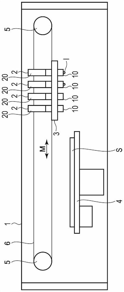
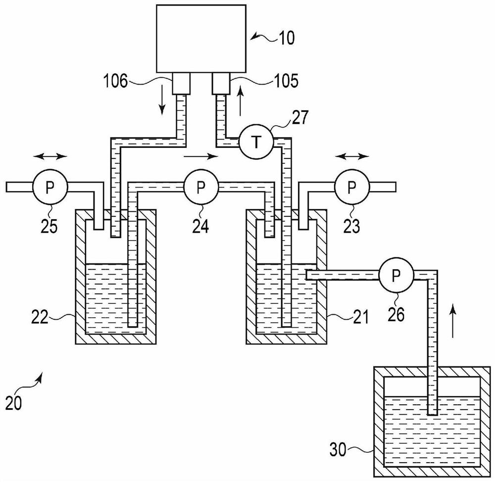
[0025] figure 1 A block diagram showing an example of the configuration of the main portion of the inkjet recording apparatus 1 according to the embodiment.

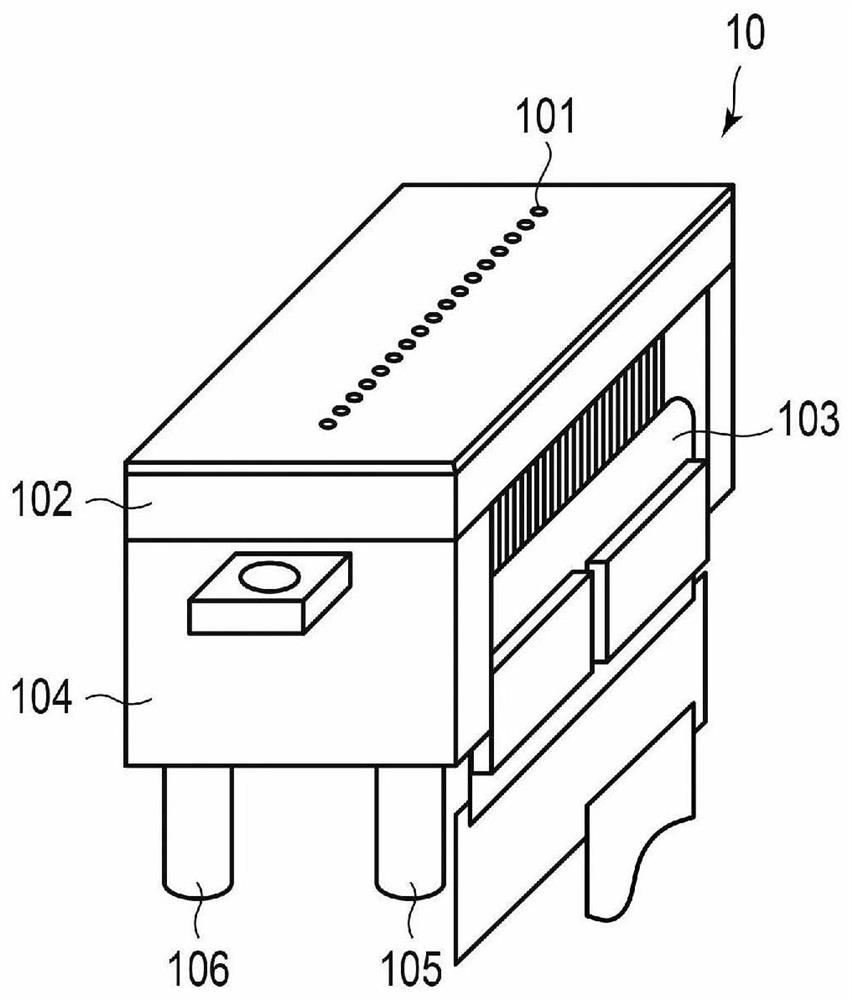
[0026] The inkjet recording apparatus 1 forms an image on the image forming medium S or the like using liquid-like recording materials such as ink. As an example, the inkjet recording apparatus 1 includes a plurality of liquid ejection portions 2, which can be moved to support the head support mechanism 3 of the liquid ejection portion...


PUM


Abstract

The invention provides a liquid ejection head and a liquid ejection device, by which, the discharge amount can be changed without changing the nozzle structure. According to one embodiment, a drive signal includes an auxiliary pulse, an ejection pulse, a cancel pulse, and a damping pulse, in this order. The auxiliary pulse drives an actuator so that the pressure is increased. The ejection pulse drives the actuator so that the pressure is reduced to eject the liquid. The cancel pulse drives the actuator so that the pressure is increased to suppress residual vibration of the liquid. The damping pulse drives the actuator so that the pressure is reduced to suppress the residual vibration. A pulse width of the auxiliary pulse is AL or less . A pulse width of the cancel pulse is 2 AL. A length from an end of the application of the cancel pulse to a start of the application of the damping pulse is 0.2 AL to 0.4 AL. A pulse width of the damping pulse is 0.2 AL to 0.4 AL.

Description

Technical field [0001] Embodiments of the invention relate to liquid discharge heads and liquid discharge devices. Background technique [0002] A liquid ejection device (inkjet printer) having a liquid ejection head (inkjet head) of liquid discharge head (inkjet head) is mounted from the nozzle is discharged. Such a liquid discharge head is ejected by the action of the actuator by applying a drive signal to the actuator. At present, in the driving mode of the liquid ejection head, in order to change the amount of liquid droplets, a change of the nozzle structure is required, for example, the diameter of the nozzle is changed, and the actuator is changed to an actuator having a different intensity, and the like. In addition, when the shape of the nozzle changes, the print quality will also change, so the adjustment of the drive waveform is time consuming. [0003] Patent Document 1: Japanese Laid-Open No. 2007-30311 Inventive content [0004] The technical problem to be solved b...

Claims


Application Information

Patent Timeline
IPC IPC(8): B41J2/14
CPCB41J2/14032B41J2/04581B41J2/04588B41J2/04595B41J2/04596B41J2202/10
Inventor 伊藤祥太
Owner TOSHIBA TEC KK
Why Eureka
Try Eureka