Control device for suppression of residual vibration of piezoelectric transducer

a control device and piezoelectric transducer technology, applied in piezoelectric/electrostrictive/magnetostrictive devices, piezoelectric/electrostriction/magnetostriction machines, instruments, etc., can solve problems such as inability to sense obstacles in the blind rang

Inactive Publication Date: 2013-08-20
TUNG THIH ELECTRONICS
View PDF7 Cites 3 Cited by
  • Summary
  • Abstract
  • Description
  • Claims
  • Application Information

AI Technical Summary

Benefits of technology

[0010]Therefore, an object of the present invention is to provide a control device for suppression of residual vibration of a piezoelectric transducer that can ensure convergence of the residual vibration.
[0011]Accordingly, the control device for suppression of residual vibration of a piezoelectric transducer, which is applied in a system with an equivalent mass block, of this invention includes a capacitive energy storage component, and a switch unit. The switch unit is coupled electrically to the capacitive energy storage component, and is for coupling electrically to the piezoelectric transducer. The control device is operable in a non-working mode, in which the switch unit provides voltage on the capacitive energy storage component to the piezoelectric transducer for reducing the residual vibration of the piezoelectric transducer.

Problems solved by technology

Nevertheless, after emission of the ultrasonic wave signal, the piezoelectric transducer and the aluminum shell could not stop vibrating right away due to their elasticity and the residual vibration will damp away as the energy being drained to overcome frictional or other resistive forces.
Obstacles in the blind range could not be sensed since the echo signal reflected by it reaches the parking sensor while it is still in the residual vibration and the parking sensor could not distinguish the echo signal from the residual vibration.

Method used


Image

  • Control device for suppression of residual vibration of piezoelectric transducer
  • Control device for suppression of residual vibration of piezoelectric transducer
  • Control device for suppression of residual vibration of piezoelectric transducer

Examples


Embodiment Construction

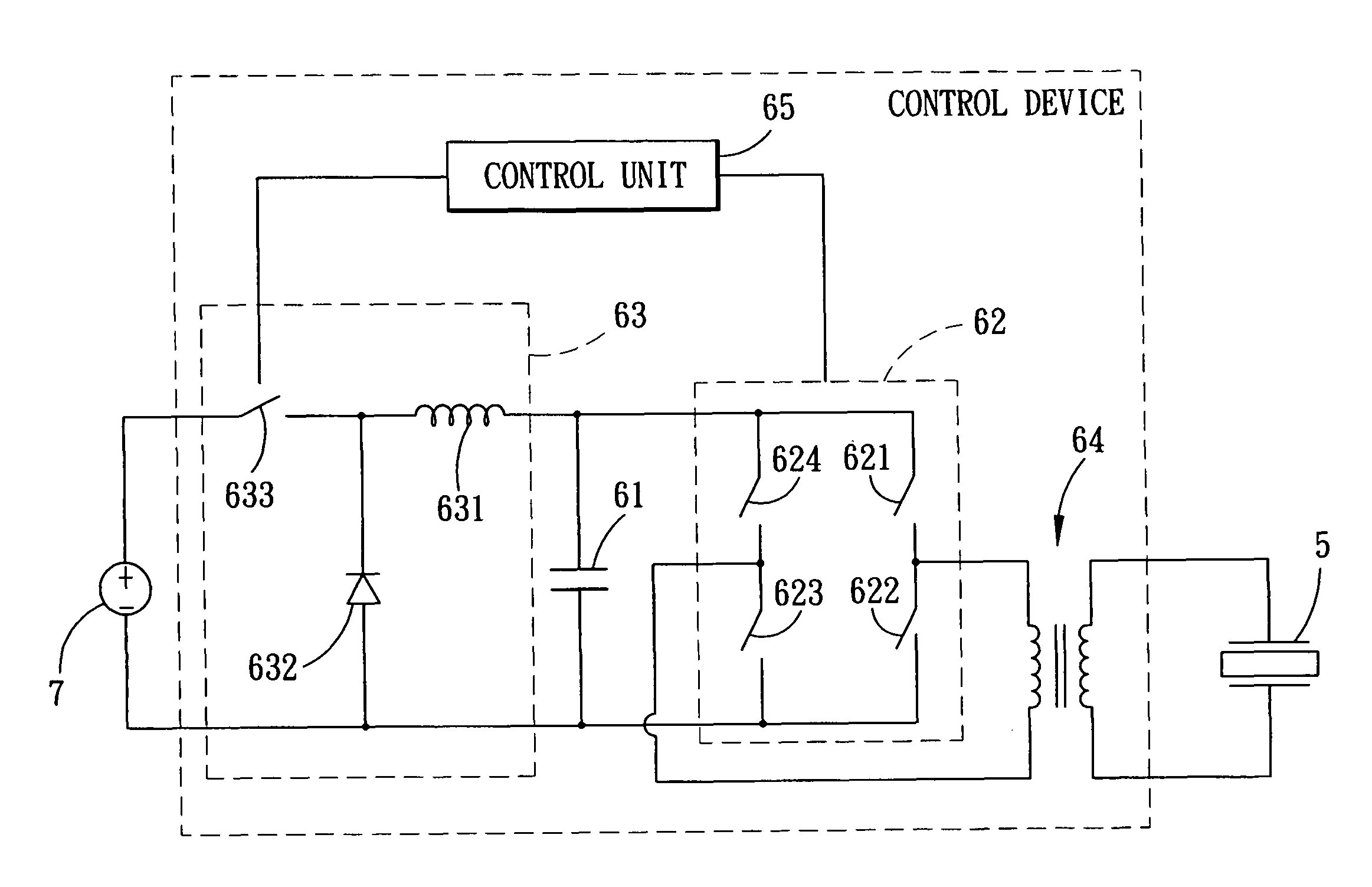
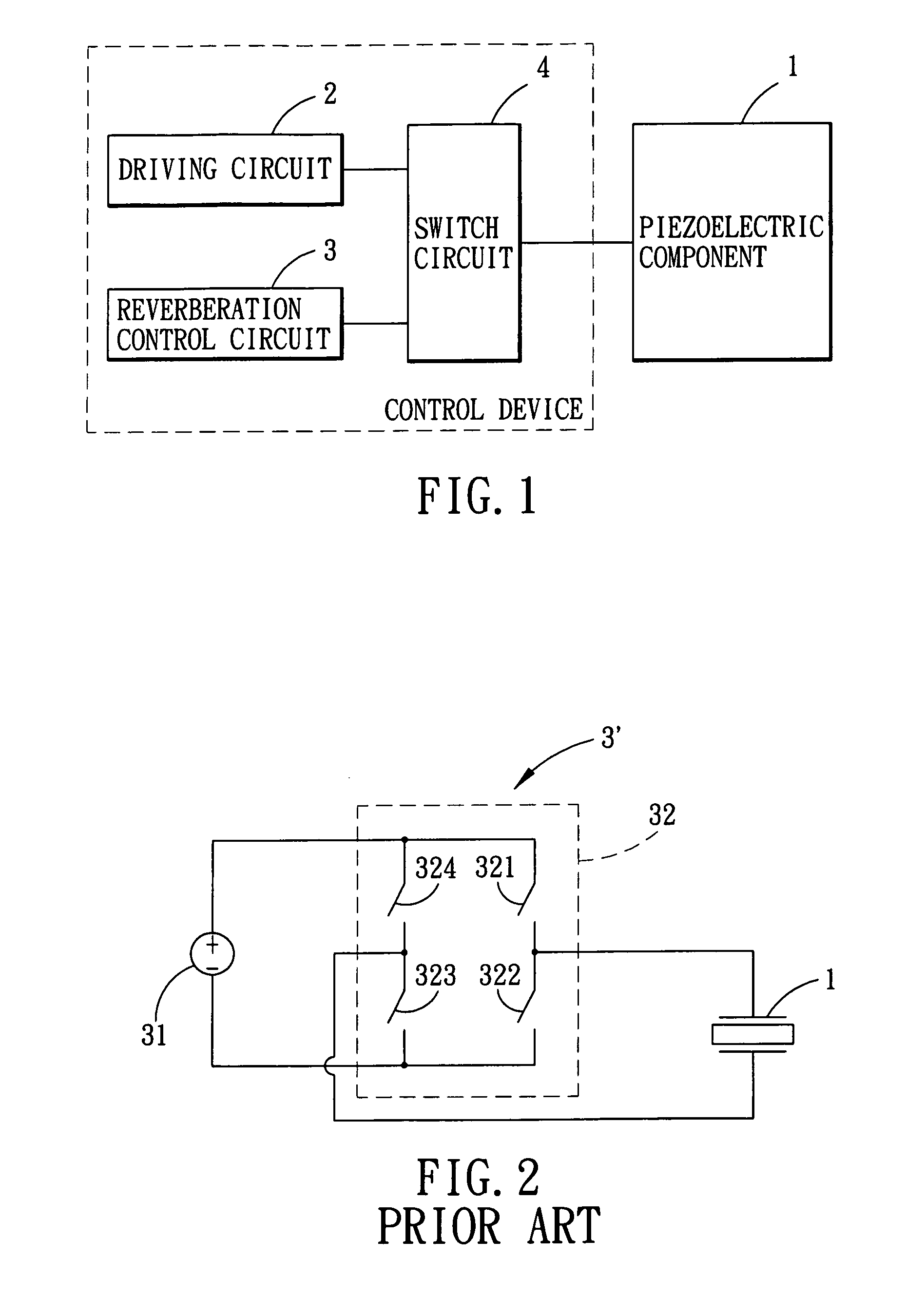
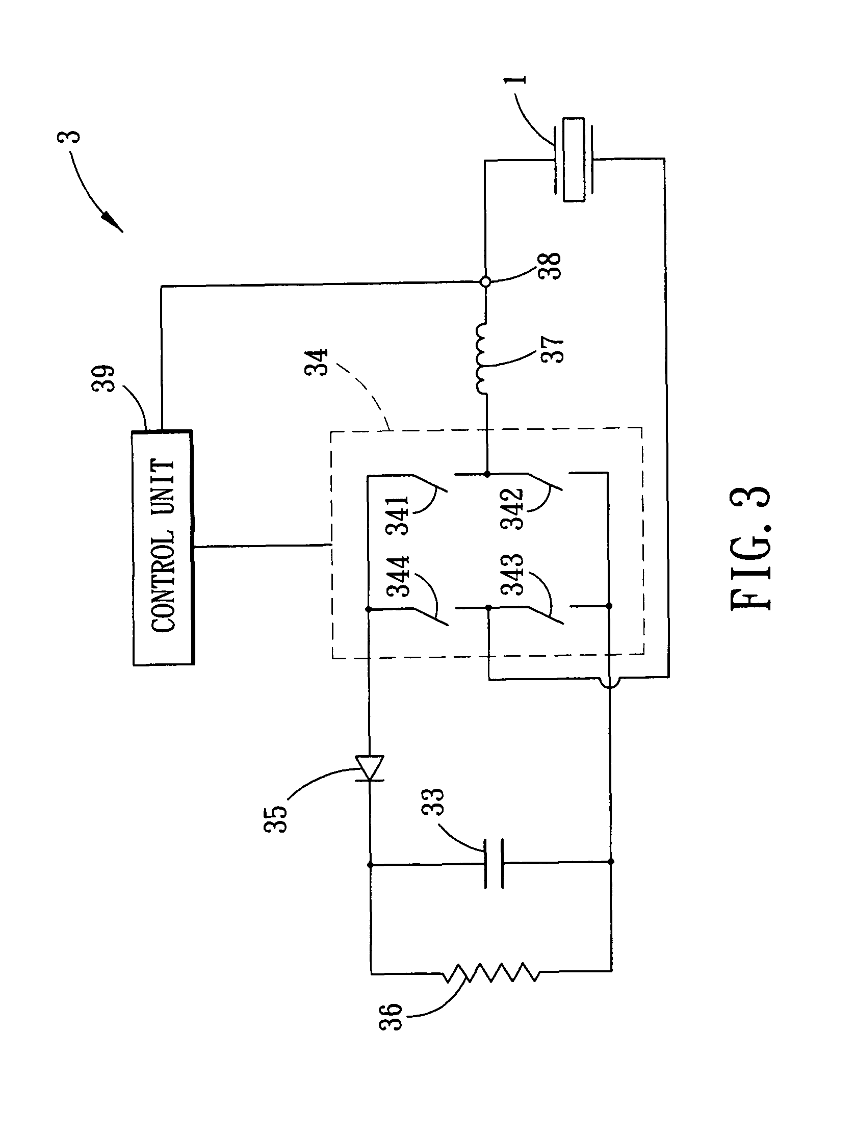
[0025]Referring to FIG. 1 and FIG. 3, a first preferred embodiment of a control device for suppression of residual vibration of a piezoelectric transducer of the present invention includes a driving circuit 2, a residual control circuit 3, and a switch circuit 4. The control device is operable in a working mode and a non-working mode. Under the working mode, the switch circuit 4 couples the driving circuit 2 electrically to a piezoelectric transducer 1 and the driving circuit 2 outputs a sinusoidal electric current as a driving signal for driving the piezoelectric transducer 1 to vibrate. Under the non-working mode, the switch circuit 4 couples the residual control circuit 3 electrically to the piezoelectric transducer 1, and the residual control circuit 3 suppresses residual vibration of the piezoelectric transducer 1. During residual vibration of the piezoelectric transducer 1, the piezoelectric transducer 1 outputs an electric current due to piezoelectricity. The electric current...


PUM


Abstract

A control device for suppression of residual vibration of a piezoelectric transducer includes a capacitive energy storage component, and a switch unit. The control device is operable in a non-working mode, in which the switch unit provides voltage on the capacitive energy storage component to the piezoelectric transducer for reducing the residual vibration of the piezoelectric transducer. The capacitive energy storage component has a capacitance value that is sufficient for enabling the voltage on the capacitive energy storage component to substantially track voltage on the piezoelectric transducer under the non-working mode.

Description

CROSS-REFERENCE TO RELATED APPLICATION[0001]This application claims priority of Taiwanese Application No. 099131709, filed on Sep. 17, 2010.BACKGROUND OF THE INVENTION[0002]1. Field of the Invention[0003]The present invention relates to a control device, more particularly to a control device for suppression of residual vibration of a piezoelectric transducer.[0004]2. Description of the Related Art[0005]A parking sensor is usually implemented by using aluminum shell stuck with a piezoelectric transducer. When a driving signal is transmitted to the parking sensor, the piezoelectric transducer will transform electrical energy into mechanical force due to piezoelectricity so as to cause the aluminum shell to vibrate for generating an ultrasonic wave signal. After the emission of the ultrasonic wave signal, the parking sensor will transfer into the sensing mode and keep sensing an echo signal which was generated by reflection of the ultrasonic wave signal when bumping into an obstacle. B...

Claims


Application Information

Patent Timeline
Patent Type & Authority Patents(United States)
IPC IPC(8): H01L41/113G01S15/931
CPCG10K11/002G01S15/931G01S2013/9314
Inventor WU, CHAO-TINGWU, WEN-JONG
Owner TUNG THIH ELECTRONICS
Why Eureka
Try Eureka