Projection system, projection lens module, optical actuator and its driving method

a projection lens and actuator technology, applied in the direction of instruments, printers, cameras, etc., can solve the problems of inability to commercialize the transmissive optical actuator under spatial limitations, and the need for feedback control, so as to reduce residual vibration, reduce driving force, and enhance the performance of the optical actuator

Active Publication Date: 2011-04-26
DELTA ELECTRONICS INC
View PDF2 Cites 0 Cited by
  • Summary
  • Abstract
  • Description
  • Claims
  • Application Information

AI Technical Summary

Benefits of technology

In view of the foregoing, the present invention is to provide a projection lens module, an optical actuator and a driving method of the optical actuator capable of reducing the driving force and the residual vibration and of being applied to an optical transmissive product to enhance the utility and the performance.
As mentioned above, in the projection system, projection lens module, optical actuator and driving method thereof of the present invention, the first and second acceleration-deceleration sections of the driving signal can drive the optical element to shift between two positions. Thus, the driving method based on the acceleration-deceleration sections has the reduced driving force and the reduced residual vibration as compared with the prior art method based on the specific waveform, so that the performance of the optical actuator can be enhanced. In addition, because the required driving force is smaller, the optical actuator having the lower rigidity can be used in the present invention, and the optical actuator can be combined within the lens module, so that the space is saved and the utility can be enhanced.

Problems solved by technology

However, the transmissive optical actuator is not commercialized under the spatial limitation and the large swinging angle which has to be 50 times of that of the reflective optical actuator.
However, the drawback is that the feedback control is needed.

Method used


Image

  • Projection system, projection lens module, optical actuator and its driving method
  • Projection system, projection lens module, optical actuator and its driving method
  • Projection system, projection lens module, optical actuator and its driving method

Examples


Embodiment Construction

The present invention will be apparent from the following detailed description, which proceeds with reference to the accompanying drawings, wherein the same references relate to the same elements.

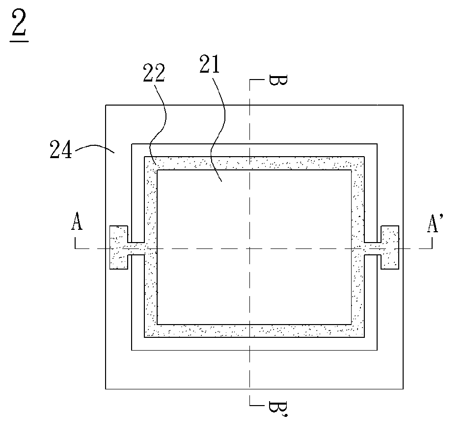
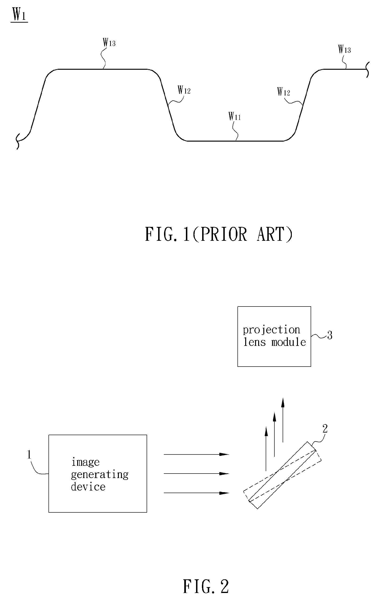
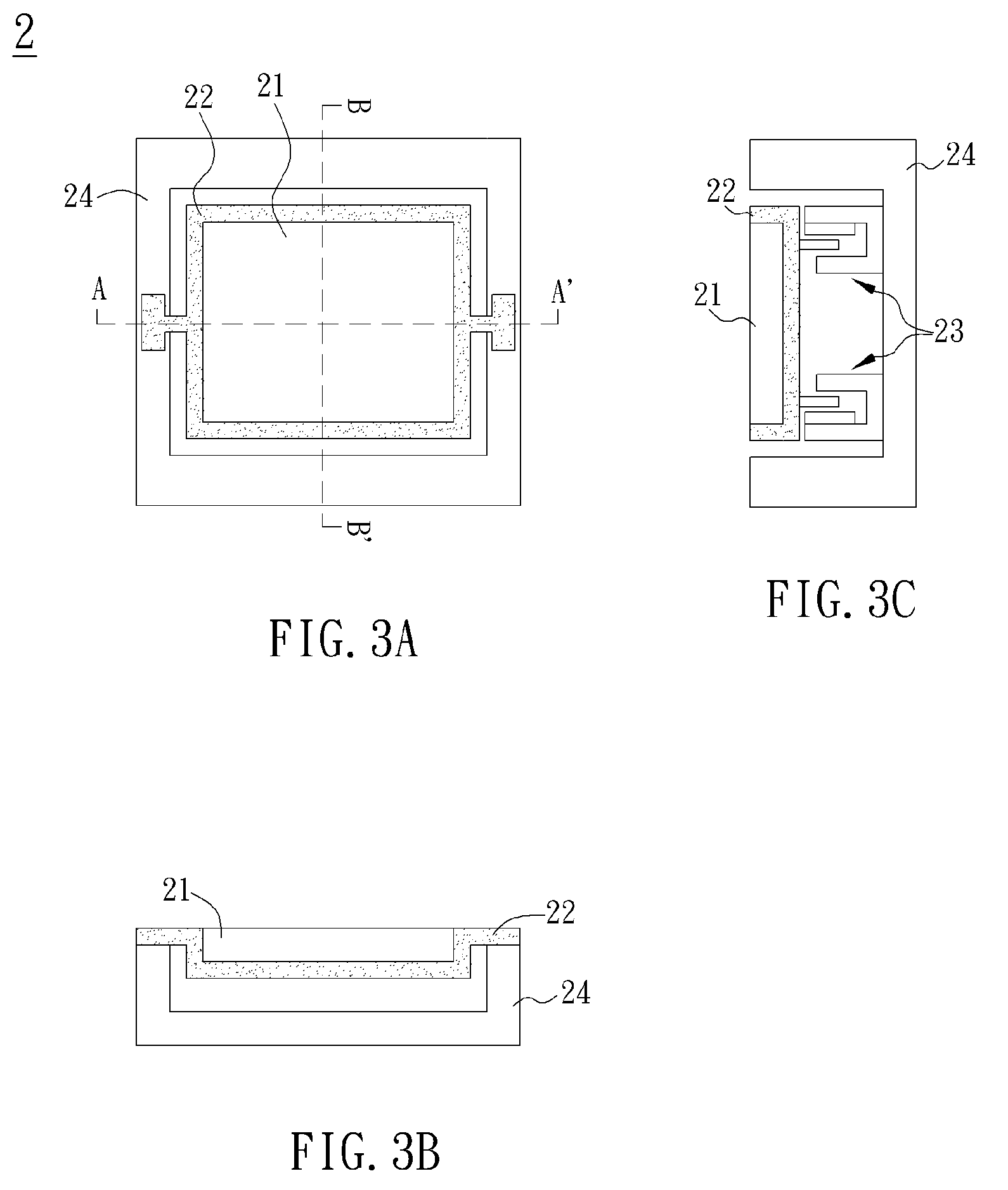
A driving method of an optical actuator according to the embodiment of the present invention can be applied to a projection system such as a front projection system or a rear projection system. Referring to FIG. 2, the projection system includes an image generating device 1, an optical actuator 2 and a projection lens module 3. Herein, the optical actuator 2 is a reflective optical actuator, for example.

The image generating device 1 generates an image according to the DMD, 3LCD panels or LCoS panel technology, which is frequently used in the industry. The projection lens module 3 projects the image onto a screen. The optical actuator 2 can swing repeatedly so that the image can be reflected to at least two positions via the optical actuator 2 and enter the projection lens module 3. Accordin...


PUM


Abstract

A driving method of an optical actuator is applied to a projection system. The optical actuator includes a carrier, an optical element and an actuator component. The optical element is disposed at the carrier. The actuator component drives the carrier to rotate an angle. The driving method includes the steps of providing a driving signal having an initial section and a target section, and shifting the optical element between a position driven by the initial section and a position driven by the target section via the actuator component according to a first acceleration-deceleration section and a second acceleration-deceleration section. In addition, an optical actuator, a projection lens module and a projection system are also disclosed.

Description

CROSS REFERENCE TO RELATED APPLICATIONSThis Non-provisional application claims priority under 35 U.S.C. §119(a) on Patent Application No(s). 096147918 filed in Taiwan, Republic of China on Dec. 14, 2007, the entire contents of which are hereby incorporated by reference.BACKGROUND OF THE INVENTION1. Field of InventionThe present invention relates to a projection system, a projection lens module, an actuator and a driving method of the actuator. More particularly, the present invention relates to a projection system, a projection lens module, an optical actuator and a driving method of the optical actuator.2. Related ArtIn general, an optical actuator is applied to a projection system in order to increase the number of pixels and smooth an image. The projection system includes an image generating device and a projection lens module. The image generating device generates the image according to the technology of digital micro-mirror devices (DMDs), three liquid crystal displays (3LCD) o...

Claims


Application Information

Patent Timeline
Patent Type & Authority Patents(United States)
IPC IPC(8): G02B26/08
CPCG02B26/085
Inventor HSU, FU-MEIKUO, CHIN-WEI
Owner DELTA ELECTRONICS INC
Why Eureka
Try Eureka