Machine tool

a technology of machine tools and machinable areas, applied in the field of machine tools, can solve the problems of limited responsiveness and inability to respond, and achieve the effect of expanding the machinable area and removing the overhang of the spindle head

Inactive Publication Date: 2007-07-03
DMG MORI CO LTD
View PDF18 Cites 2 Cited by
  • Summary
  • Abstract
  • Description
  • Claims
  • Application Information

AI Technical Summary

Benefits of technology

[0007]In view of the above-described conventional circumstances, it is an object of the present invention to provide a machine tool that is capable of responding to the demand for higher acceleration / deceleration speed by reducing residual vibration occurring at the locating time.
[0009]In this invention, the pair of right and left spindle drive shafts for driving the spindle head are disposed to be substantially symmetrical to each other with respect to the plane that includes the axis of the spindle head and is parallel to the Y axis, thereby driving the vicinity of the gravity center of the spindle head. Therefore, an imaginary driving position by the right and left spindle drive shafts can substantially match the gravity center of the spindle head to allow gravity center driving of the spindle head. This can reduce the occurrence of residual vibration that is caused by a bending moment when the spindle head is located. As a result, the aforesaid responsiveness to driving-transmission-output system can be enhanced, so that it is possible to respond to the recent demand for still higher acceleration / deceleration speed.
[0011]In the above-described embodiment, the column has the shape of the gate bridged over the travel range of the table, and the spindle head and the right and left spindle drive shafts are arranged on the front face of the beam of the column to be aligned along the straight line parallel to the X-axis, so that the imaginary driving position of the right and left spindle drive shafts can match the gravity center of the spindle head. This can further enhance responsiveness to the demand for higher acceleration / deceleration speed.
[0013]In the above-described embodiment, the beam of the column is displaced from the right and left legs toward the back face side of the machine tool, and the axis of the spindle head coincides with the legs, so that it is possible to eliminate the overhang of the spindle head from the column. In accordance therewith, support stiffness of the spindle head can be increased, which realizes responsiveness to higher acceleration / deceleration speed.
[0015]In the above-described embodiment, the beam is positioned at the substantially center portion of the bed in terms of the Y-axis direction, so that it is possible to position the spindle head at the center portion of the bed while eliminating the overhang of the spindle head. This can expand a machinable area.

Problems solved by technology

As the acceleration / deceleration speed at the time of the Z-axis direction feed of the spindle becomes higher and required locating accuracy becomes higher, however, the conventional driving system described above has come to have limited responsiveness to driving-transmission-output system, which poses a concern that it may not be able to respond to the recent requirement for still higher acceleration / deceleration speed.

Method used


Image

  • Machine tool
  • Machine tool
  • Machine tool

Examples


Embodiment Construction

[0024]Hereinafter, an embodiment of the present invention will be described based on the attached drawings.

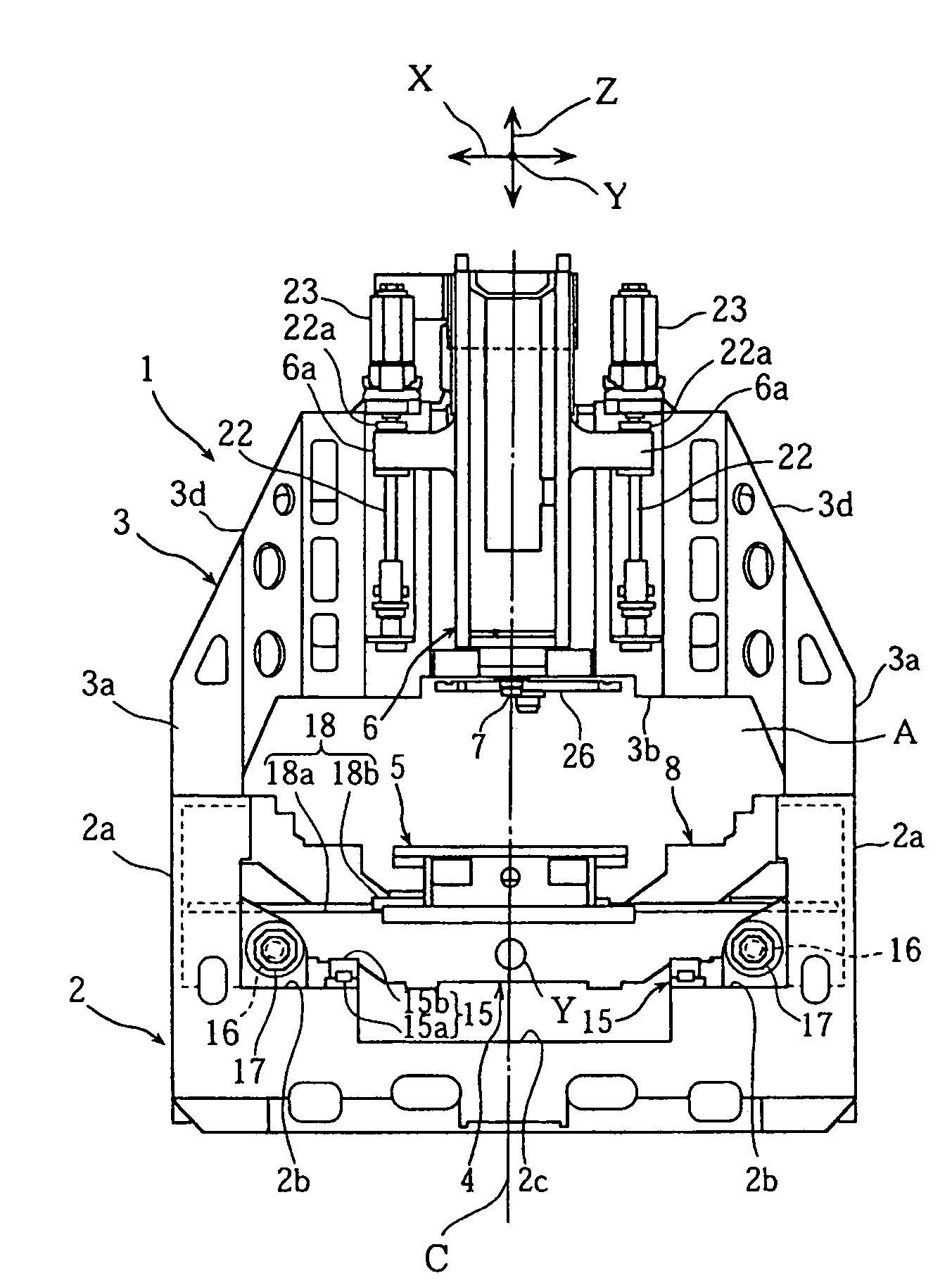
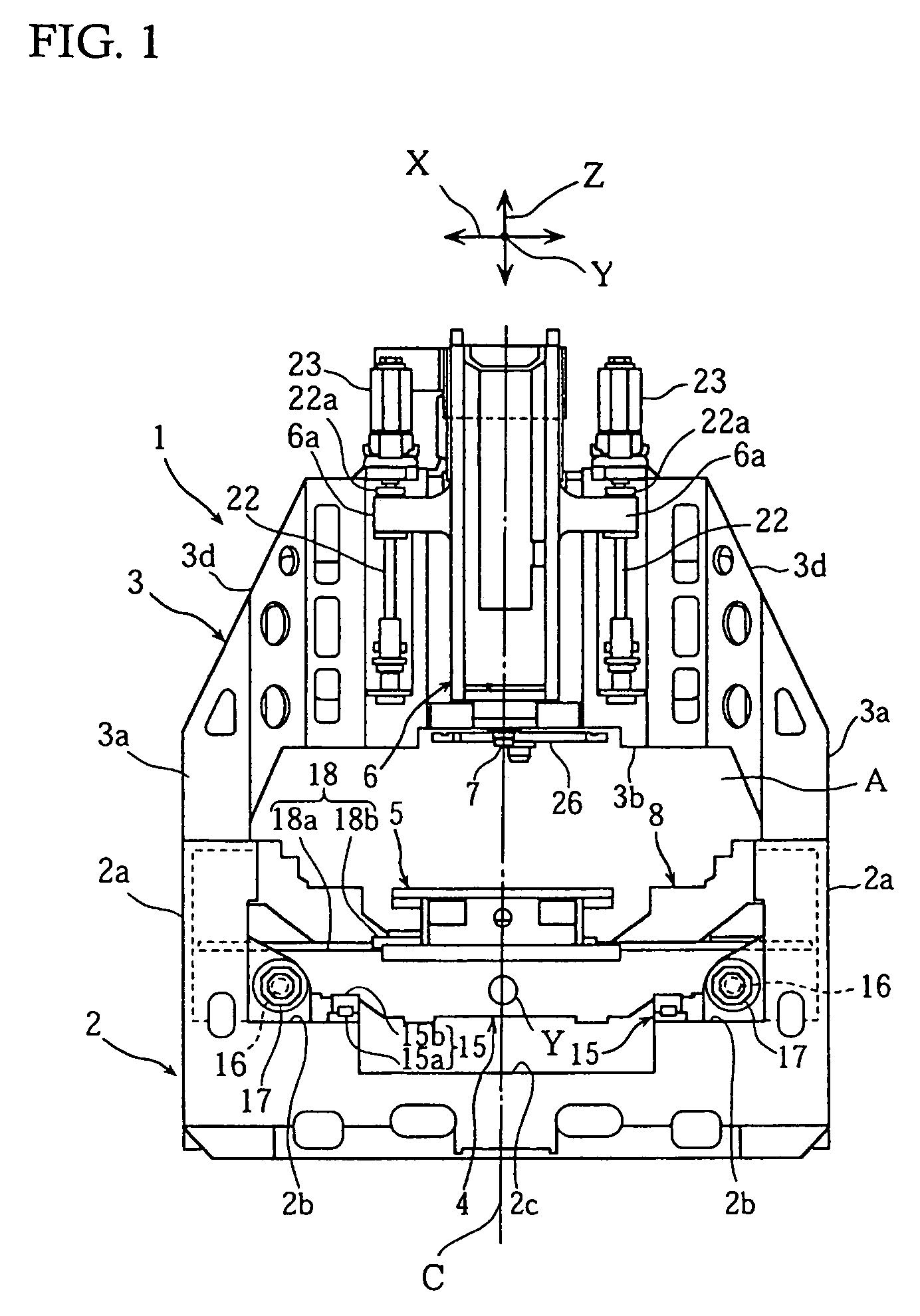
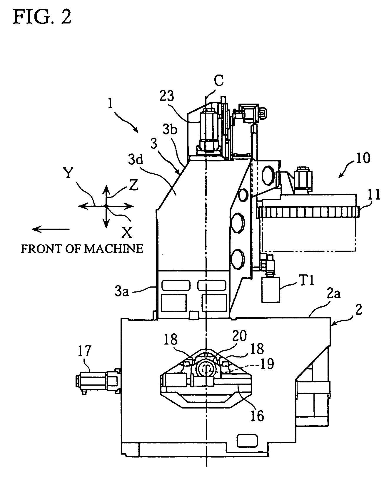
[0025]FIG. 1 to FIG. 4 are views to explain a vertical machining center (machine tool) according to an embodiment of the present invention. FIG. 1 to FIG. 4 are a front view, a right side view, a plane view, and a rear perspective view respectively of the vertical machining center on which a tool changer, a pallet changer, and a chip disposer are mounted.

[0026]In the drawings, a vertical machining center 1 includes; a gate-shaped column 3 fixed on a substantially center portion of a fixed bed 2 in terms of a forward and backward direction in a front view of the machine; a saddle 4 disposed under the column 3 to be movable in a Y-axis (forward and backward) direction; a table 5 disposed on the saddle 4 to be movable in an X-axis (right and left) direction; and a spindle head 6 disposed on a front face of the column 3 to be movable in a Z-axis (vertical) direction. A spindle 7 is...


PUM

PropertyMeasurementUnit
gravityaaaaaaaaaa
shapeaaaaaaaaaa
acceleration/deceleration speedaaaaaaaaaa

Abstract

The present invention provides a machine tool capable of reducing residual vibration occurring at the location time, thereby achieving responsiveness to a recent demand for higher acceleration / deceleration speed. The machine tool is configured such that a column 3 is fixed on a bed 2, a spindle head 6 for supporting a spindle 7 is disposed on a front face 3b′ of the column 3 to be movable in a Z-axis direction, and a pair of right and left Z-axis ball screws (spindle drive shafts) 22 for driving the vicinity of the gravity center of the spindle head 6 is disposed on the front face 3b′ of the column 3 to be symmetrical to each other with respect to a plane that includes an axis C of the spindle head 6 and is parallel to a Y axis, thereby driving the vicinity of the gravity center of the spindle head 6.

Description

BACKGROUND OF THE INVENTION[0001]1. Field of the Invention[0002]The present invention relates to a machine tool that machines a workpiece while moving a vertically set spindle and the workpiece relatively to each other in X-axis, Y-axis, and Z-axis directions.[0003]2. Discussion of the Related Art[0004]For example, a vertical machining center is generally structured, as shown in FIG. 5, to include: a column 61 fixedly disposed on a back end of a fixed bed 60 when seen from a front side of the machine; a saddle 62, for placing a workpiece W thereon, disposed on a front part of the fixed bed 60 to be movable in a Y-axis (forward and backward) direction; a table 63 disposed on the saddle 62 to be movable in an X-axis (right and left) direction; and a spindle head 65, with a spindle 64 attached thereto, disposed on a front face of the column 61 to be movable in a Z-axis (vertical) direction (see, for example, Japanese Patent Application Laid-open No. Sho 63-62636).[0005]A driving system...

Claims


Application Information

Patent Timeline
Patent Type & Authority Patents(United States)
IPC IPC(8): B23C1/06B23C1/00B23Q1/01B23Q1/00B23Q1/25B23Q5/40B23Q11/00
CPCB23Q1/015B23Q5/40B23Q11/0032Y10T409/307728Y10T409/309576Y10T409/3098Y10T409/306776
Inventor HIRAMOTO, KAZUYUKIMOCHIZUKI, AKIHIRONAKAZAWA, SHUNSUKEMATSUI, SATOSHI
Owner DMG MORI CO LTD
Why Eureka
Try Eureka