Liquid Ejecting Apparatus

a liquid ejecting and liquid technology, applied in the direction of printing, inking apparatus, etc., can solve the problem of more likely generation of mis, and achieve the effect of reducing residual vibration of liquid and reducing liquid residual vibration

Pending Publication Date: 2022-09-22
SEIKO EPSON CORP
View PDF0 Cites 0 Cited by
  • Summary
  • Abstract
  • Description
  • Claims
  • Application Information

AI Technical Summary

Benefits of technology

[0005]A liquid ejecting apparatus according to an aspect of the present disclosure includes an ejecting section including a nozzle that ejects liquid to be landed on a medium, a pressure chamber that communicates with the nozzle, and a driving element supplied with a driving signal to generate a pressure variation in liquid in the pressure chamber, and a driving-signal generation unit that generates the driving signal. The driving signal includes a plurality of ejection pulses for ejecting a plurality of droplets during one cycle. The plurality of droplets due to the plurality of ejection pulses coalesces before landing on the medium. The plurality of ejection pulses includes a final ejection pulse that corresponds to a final droplet ejected last from the nozzle among the plurality of droplets, and a preceding ejection pulse that corresponds to a preceding droplet, among the plurality of droplets, ejected from the nozzle before the final droplet. The preceding ejection pulse includes a first expansion element that expands the pressure chamber, a first expansion-maintaining element that maintains expansion of the pressure chamber by the first expansion element, a first contraction element that contracts the pressure chamber expanded by the first expansion element, and a first vibration-damping element that, after the first contraction element contracts the pressure chamber, expands the pressure chamber to reduce residual vibration of liquid in the pressure chamber. The final ejection pulse includes a second expansion element that expands the pressure chamber, a second expansion-maintaining element that maintains expansion of the pressure chamber by the second expansion element, a second contraction element that contracts the pressure chamber expanded by the second expansion element, and a second vibration-damping element that, after the second contraction element contracts the pressure chamber, expands the pressure chamber to reduce residual vibration of liquid in the pressure chamber. A time width of a sum of the second expansion element and the second expansion-maintaining element of the final ejection pulse is longer than a length that is 0.5 multiplied by a natural-vibration cycle of the ejecting section, and is shorter than a length that is 1.0 multiplied by the natural-vibration cycle of the ejecting section.

Problems solved by technology

When the speed of a droplet ejected later is made faster, however, there is a problem that a mist is more likely to be generated.

Method used


Image

  • Liquid Ejecting Apparatus
  • Liquid Ejecting Apparatus
  • Liquid Ejecting Apparatus

Examples


Embodiment Construction

[0021]Hereinafter, an embodiment of the present disclosure will be described with reference to the drawings. In each of the drawings, however, dimensions and a scale of each section are appropriately different from the actual ones. In addition, since the embodiment described below is a preferable specific example of the present disclosure, various technically preferable limitations are given. However, the scope of the present disclosure is not limited to the embodiment unless there is a description to particularly limit the present disclosure in the following description.

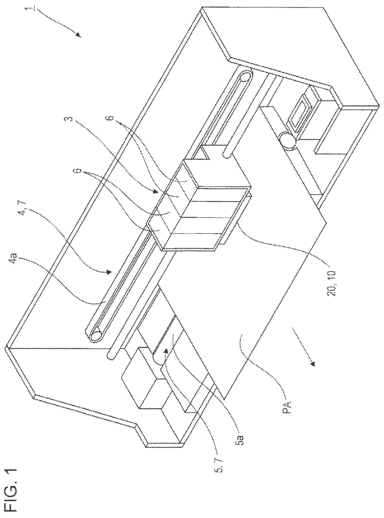
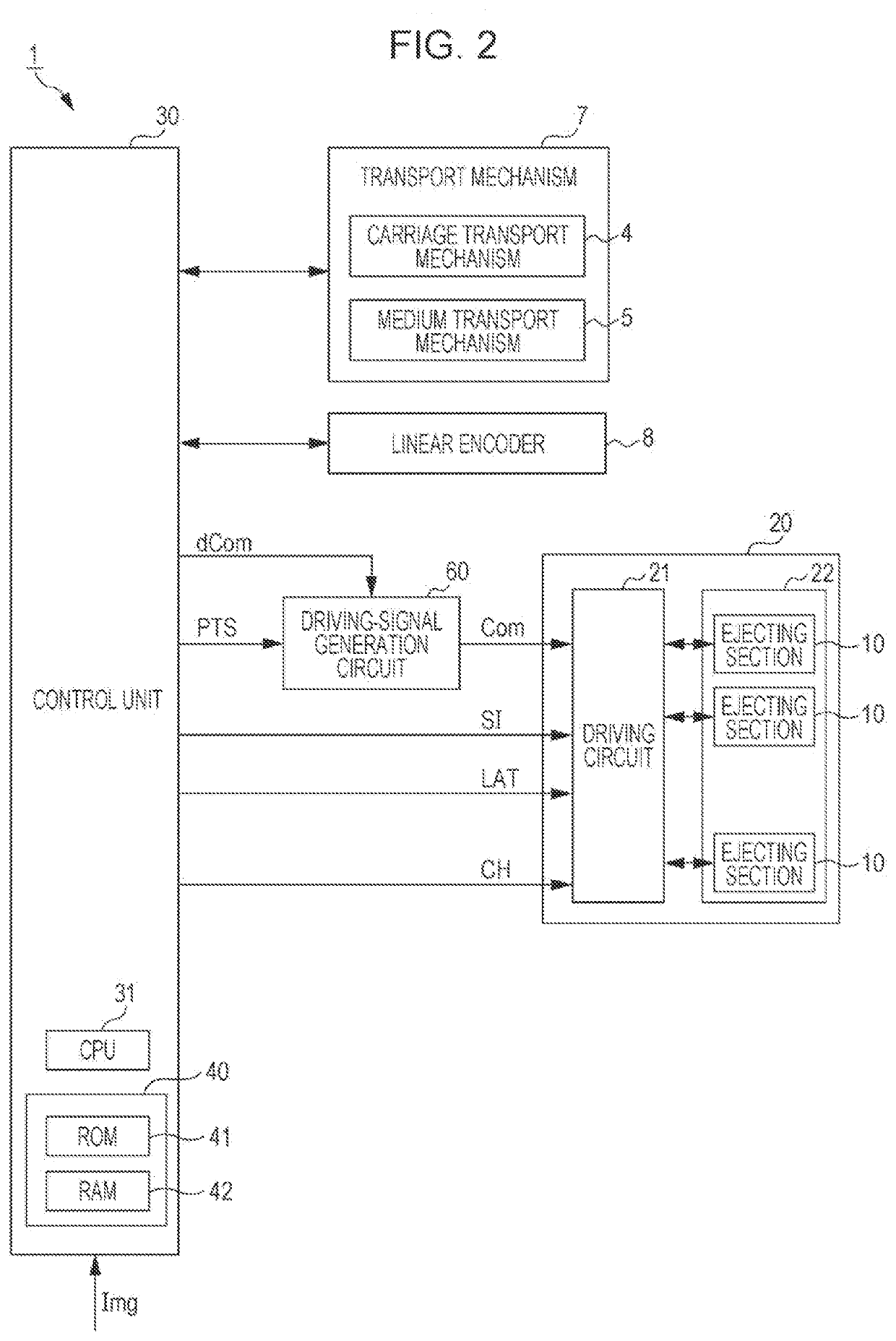
[0022]FIG. 1 is a schematic perspective view illustrating an internal configuration of a liquid ejecting apparatus 1 according to an embodiment. FIG. 2 is a block diagram illustrating the liquid ejecting apparatus 1. The liquid ejecting apparatus 1 illustrated in FIG. 1 ejects ink droplets from ejecting sections 10 to land the ink droplets on a medium PA. The medium PA is, for example, printing paper. The liquid eje...


PUM


Abstract

A liquid ejecting apparatus includes ejecting sections that eject droplets from nozzles according with a driving signal supplied thereto. The driving signal includes a plurality of ejection pulses during one cycle. The plurality of ejection pulses includes a final ejection pulse corresponding to a final droplet. The final ejection pulse includes an expansion element that expands a pressure chamber, an expansion-maintaining element that maintains the expansion of the pressure chamber, a contraction element that contracts the pressure chamber, and a vibration-damping element that reduces residual vibration of liquid in the pressure chamber. The time width of the sum of the expansion element and the expansion-maintaining element of the final ejection pulse is longer than a length that is 0.5 multiplied by the natural-vibration cycle of the ejecting sections, and is shorter than a length that is 1.0 multiplied by the natural-vibration cycle.

Description

[0001]The present application is based on, and claims priority from JP Application Serial Number 2021-047855, filed Mar. 22, 2021, the disclosure of which is hereby incorporated by reference herein in its entirety.BACKGROUND1. Technical Field[0002]The present disclosure relates to a liquid ejecting apparatus.2. Related Art[0003]A liquid ejecting apparatus described in JP-A-2017-95814 supplies a driving signal to a driving element and generates a pressure variation in liquid in a pressure chamber to eject droplets from a nozzle. The liquid ejecting apparatus makes a first ink droplet and a second ink droplet ejected from the nozzle coalesce before the first ink droplet and the second ink droplet land on a medium.[0004]A liquid ejecting apparatus in the related art supplies a driving signal including a plurality of ejection pulses having different waveform shapes to a driving element, to make a plurality of droplets coalesce before the plurality of droplets land on a medium. To make t...

Claims


Application Information

Patent Timeline
Patent Type & Authority Applications(United States)
IPC IPC(8): B41J2/045
CPCB41J2/04573B41J2/04581B41J2202/06B41J2/04516B41J2/04588B41J2/04595
Inventor HASHIMOTO, ATSUHIROTSUCHIHASHI, RYOSUKE
Owner SEIKO EPSON CORP
Why Eureka
Try Eureka