
A Vibration Control Method of Rigid-Flexible Electromechanical Servo System

An electromechanical servo system, rigid technology, applied in electric controllers, mechanical oscillation control, non-electric variable control, etc., can solve the problems of residual dynamic behavior of lightweight flexible materials, inability to accurately describe viscoelastic materials, etc.

Active Publication Date: 2021-05-25
NANJING UNIV OF AERONAUTICS & ASTRONAUTICS
View PDF19 Cites 0 Cited by
  • Summary
  • Abstract
  • Description
  • Claims
  • Application Information

AI Technical Summary

Problems solved by technology

[0003] The purpose of the present invention is to provide a vibration control method of a rigid-flexible coupling electromechanical servo system, so as to solve the problem that the vibration control method in the prior art cannot accurately describe the dynamics of light and flexible materials such as viscoelastic materials and carbon nanocomposites. Continuous residual vibration after behavior and servo control ends

Method used


Image

  • A Vibration Control Method of Rigid-Flexible Electromechanical Servo System
  • A Vibration Control Method of Rigid-Flexible Electromechanical Servo System
  • A Vibration Control Method of Rigid-Flexible Electromechanical Servo System

Examples


Embodiment Construction

[0027]The technical solutions of the present invention will be described below in conjunction with the drawings, as will be described, as described herein is an embodiment of the invention, not all of the embodiments. Based on the embodiments of the present invention, there are all other embodiments obtained without making creative labor without making creative labor premises.

[0028]In the description of the invention, it is to be described in the terms "center", "upper", "lower", "left", "right", "vertical", "horizontal", "within", "outside", etc. The orientation or positional relationship indicated is based on the orientation or positional relationship shown in the drawings, is merely intended to describe the present invention and simplified description, rather than indicating or implying that the device or component must have a specific orientation. Construct and operation, so it is not understood to be the limitation of the invention. Moreover, the term "first", "second", "third"...


PUM


Abstract

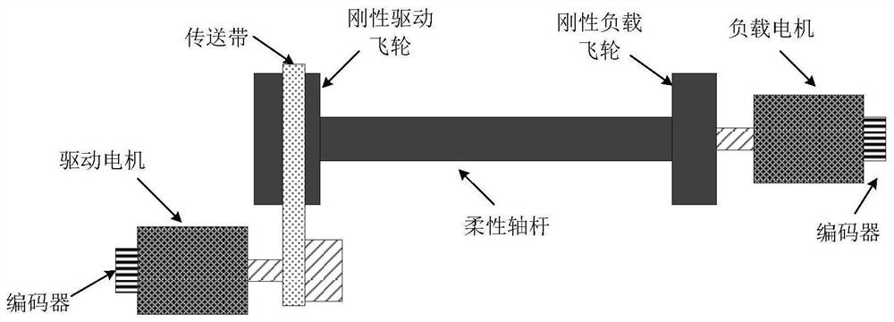
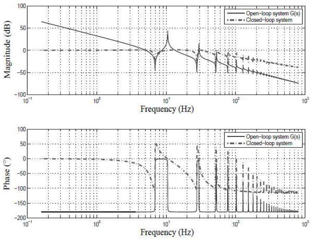
The invention discloses a vibration control method of a rigid-flexible coupling electromechanical servo system, comprising: separately collecting encoder data on a drive motor and a load motor, obtaining the torsion angles at both ends of a flexible shaft in real time, and calculating the flexible shaft The torsion angle of the micro-element at any position on the above is calculated according to the length, polar moment of inertia, elastic modulus and moment of inertia of the flexible shaft to obtain the frequency domain characteristic equation; using the frequency domain characteristic equation to calculate the described The coupling torque between the flexible shaft and the rigid drive flywheel; the balance equation of the rigid drive flywheel is established; the coupling torque is brought into the balance equation to obtain the fractional transfer function model of the system; according to the fractional transfer function model, establish a fractional order controller, and use the controller to control the vibration of the system. The method involved in this patent accurately describes the dynamic behavior of the viscoelastic material through the fractional order model, and effectively suppresses the residual vibration of the system.

Description

Technical field[0001]The present invention relates to the field of power and transmission, in particular, to a vibration control method of a rigid-flexible electromechanical servo system.Background technique[0002]Rigid-soft coupling electromechanical servo system is widely used in aerospace, mechanical manufacturing, robot and other industrial fields. The system is composed of a drive motor and an encoder, a conveyor belt, a rigid drive aircraft, a flexible shaft, a rigid load average, a load motor, and an encoder. In order to improve system response speed and reduce power consumption, the flexible shaft is made of lightly flexible viscoelastic material, which in turn forms a mechanical and electrical servo system coupled to each other with rigid flywheels and flexible shafts. The presence of the flexible structure will cause the system to generate continuous residual vibration after the end of servo control, weaken the servo control accuracy, and even hazardously harm the productio...

Claims


Application Information

Patent Timeline
Patent Type & Authority Patents(China)
IPC IPC(8): G05D19/02G05B11/42
CPCG05B11/42G05D19/02
Inventor 徐世东文浩金栋平
Owner NANJING UNIV OF AERONAUTICS & ASTRONAUTICS
Learn More