Drive and guide arrangement for a flap which is arranged on an aircraft mainplane

a technology of driving and guiding arrangement and aircraft mainplane, which is applied in the direction of wing adjustment, wings, transportation and packaging, etc., can solve the problems of large drag, unsatisfactory drive torque profile of the apparatus according to the prior art, and achieve low drive load, small dimensions, and improved aerodynamic characteristics of the wing

Active Publication Date: 2011-01-04
AIRBUS OPERATIONS GMBH
View PDF20 Cites 11 Cited by
  • Summary
  • Abstract
  • Description
  • Claims
  • Application Information

AI Technical Summary

Benefits of technology

[0005]The object of the invention is to achieve a more uniform drive torque profile over the extension movement of the flap, and a more compact design.
[0007]The apparatus according to the invention has a number of advantages. It carries out complex guidance tasks even with more than three plane positions as well as large translational movements of the flap with small dimensions and with low drive loads. Small dimensions lead to small fairings which are to be used to cover drive and guidance apparatuses underneath the mainplane, and this in turn leads to an improvement in the aerodynamic characteristics of the wing. More than three plane positions have to be provided particularly in the case of continuous flap movements, which can be integrated for the variation of the wing profile curvature in future high-lift systems.
[0008]Since, in contrast to many other systems, the apparatus does not include any carriage as a thrust joint, there is also no need to prevent jamming situations occurring on this element. Since rotating joints can be regarded as being free of jamming, the elements of the apparatus according to the invention are designed for the loads which occur during operation. These loads are normally below the level of fault-dependent loads. This in turn results in a drive and guidance apparatus according to the invention being lighter in weight.
[0009]The arrangement of the elements allows the mechanical drive either to be integrated in the flap mount or to be arranged in the area behind a rear spar of the mainplane. Integration in the flap mount offers the advantage of clear load introduction into the wing using the mount structure, which is present in any case, to assist the drive, and without any additional mount being required for the drive. The small amount of space behind the rear spar remains free for the integration of other systems.
[0010]The accommodation of the drive in the space behind the rear spar has the advantage that the mechanical drive power need not be passed via shafts and transmissions from the area behind the rear spar to the flap mount. The mechanical drive train at the rear spar can in fact be passed through virtually in a straight line on the rear spar.

Problems solved by technology

This apparatus according to the prior art has an unsatisfactory drive torque profile over the extension movement of the flap.
The apparatus requires a large fairing and thus produces a large amount in drag during cruising flight.

Method used


Image

  • Drive and guide arrangement for a flap which is arranged on an aircraft mainplane
  • Drive and guide arrangement for a flap which is arranged on an aircraft mainplane
  • Drive and guide arrangement for a flap which is arranged on an aircraft mainplane

Examples


Embodiment Construction

[0043]The description above and below and the drawings of the present document focus on one or more currently preferred embodiments of the present invention and also describe some exemplary optional features and / or alternative embodiments. The description and drawings are for the purpose of illustration and not limitation. Those of ordinary skill in the art would recognize variations, modifications, and alternatives. Such variations, modifications, and alternatives are also within the scope of the present invention. Section titles are terse and are for convenience only.

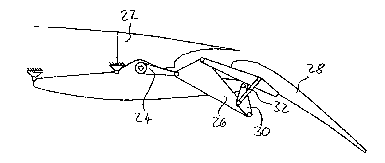
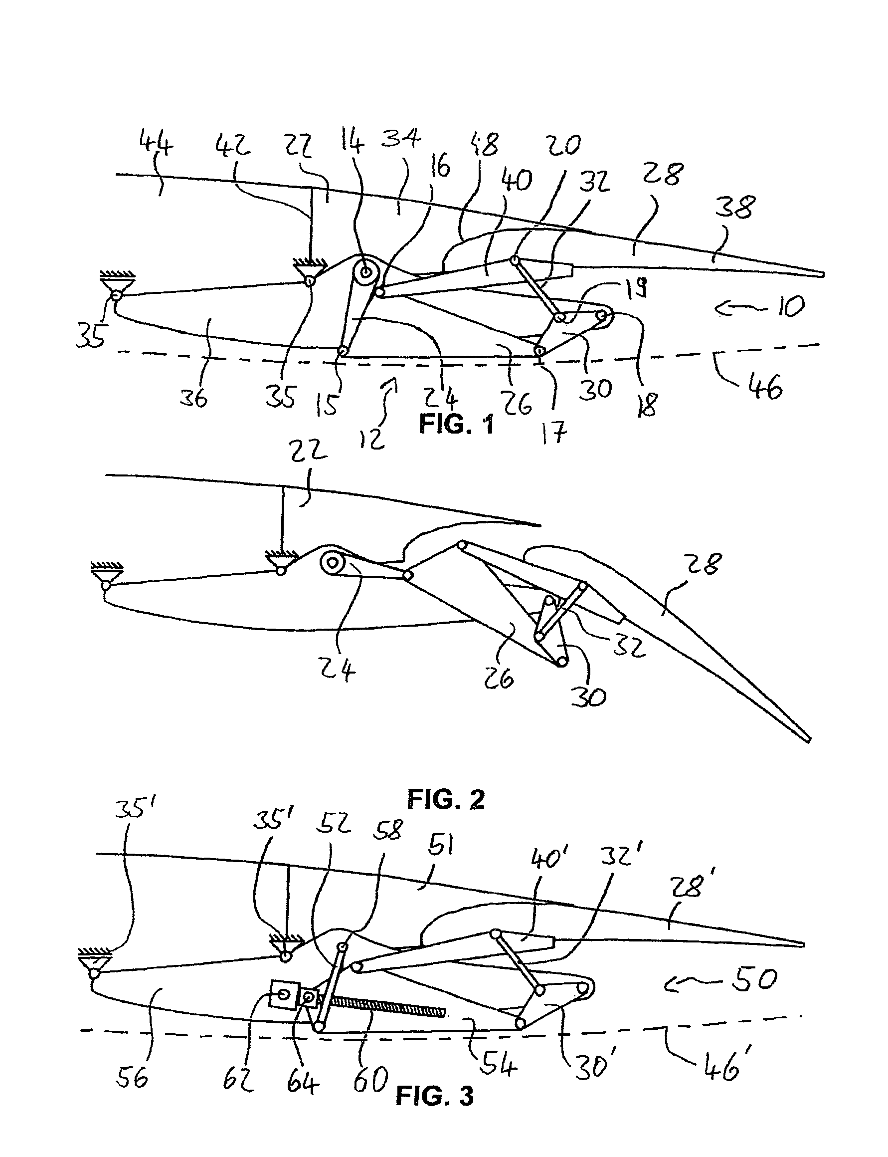
[0044]FIG. 1 shows a drive and guidance apparatus 10 according to the invention for the starboard wing, viewed from the aircraft fuselage. This apparatus 10 comprises a six-element guide chain 12 with seven rotating joints 14-20 of the kinematic Watt-I chain type with one or more shafts. In this case, a first coupling element 26, which is mounted via a crank 24 that is connected to the starboard wing of the aircraft m...


PUM


Abstract

A drive and guidance apparatus for a trailing-edge / landing flap,-arranged on an aircraft mainplane, the apparatus comprising a six-element guide chain having seven rotating joints and one or more shafts; a first coupling element mounted via a crank connected to the mainplane wherein the crank can rotate, the coupling is connected to the flap and to a second coupling element wherein the first coupling can rotate, the second coupling mounted on the mainplane wherein the second coupling can rotate. The second coupling element is connected to the flap via an oscillating support. The crank is arranged wherein the rotation direction of the crank for extension of the flap corresponds to the rotation direction of the crank for the trailing-edge flap of the starboard wing of the mainplane, with the rotation direction of the crank for the trailing-edge flap of the starboard wing being counterclockwise when viewed from the aircraft fuselage.

Description

FIELD OF THE INVENTION[0001]The invention relates to a drive and guidance apparatus for a flap which is arranged on an aircraft mainplane, in particular for a trailing-edge or landing flap.BACKGROUND OF THE INVENTION[0002]A large number of drive and guidance apparatuses are known for flaps which are arranged on aircraft mainplanes, with a suitable kinematic type being used depending on the aerodynamic and structural constraints. A summary is provided by Holert, Carl, “Interdisziplinäre Synthese von Klappenführungsmechanismen, Deutscher Luft- und Raumfahrtkongress”, Stuttgart 2002, DGLR-JT2002-155 [Interdisciplinary synthesis of flap guidance mechanisms, German Aviation and Spaceflight Congress].[0003]This document describes a drive and guidance apparatus for a flap, which is arranged on an aircraft mainplane, for a trailing-edge or landing flap, as is illustrated in FIG. 4. The drive and guidance apparatus 100 illustrated there for the starboard wing comprises, when viewed from the ...

Claims


Application Information

Patent Timeline
Patent Type & Authority Patents(United States)
IPC IPC(8): B64C3/50
CPCB64C9/16
Inventor HOLERT, BEN
Owner AIRBUS OPERATIONS GMBH
Why Eureka
Try Eureka