Exercise apparatus with rotational grips

a technology of exercise apparatus and rotating grip, which is applied in the field of weightlifting apparatus, can solve the problems of increasing wrist and elbow strain, unable to use a conventional barbell, and inability to perform the same exercise with a conventional barbell

Active Publication Date: 2011-01-04
SPINGRIP FITNESS
View PDF21 Cites 70 Cited by
  • Summary
  • Abstract
  • Description
  • Claims
  • Application Information

AI Technical Summary

Problems solved by technology

The same exercise cannot be performed with a conventional barbell because the hands and wrists are in a fixed position.
Thus, it is not possible to use a conventional barbell to exercise the groups of muscles involved in pronation and supination as with dumbbells.
Moreover, maintaining such a fixed position during exercises with the barbell increases strain on the wrists and elbows.
While these devices address the need for a rotational grip barbell, the designs of these devices create a high level of friction and instability.
Particularly, the configuration of these devices results in metal-on-metal contact or the bearings do not address sidewall loads on the grip housings.
The friction and instability causes the grips to freeze or stick in place, presenting a significant risk of injury.
Moreover, the prior art does not address the need for a rotational grip barbell that is adapted to utilize cable exercise equipment.

Method used


Image

  • Exercise apparatus with rotational grips
  • Exercise apparatus with rotational grips
  • Exercise apparatus with rotational grips

Examples


Embodiment Construction

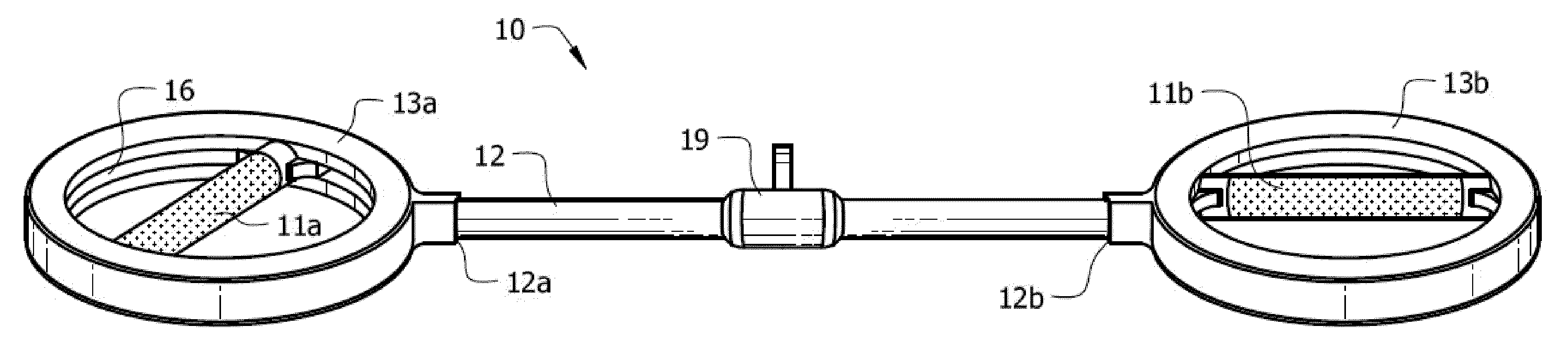
[0025]Referring now to FIG. 4, it will there be seen that the reference numeral 10 indicates an illustrative embodiment of the invention as a whole.

[0026]Barbell 10 includes rotational grips at its opposite ends. The rotational grips allow the user to exercise the groups of muscles involved in pronation and supination, and reduces strain on the wrists and elbows. The bearing configuration and a constant spring pressure eliminates the risk of the handgrips freezing or sticking in place under load. The barbell is preferably used in conjunction with cable exercise equipment.

[0027]Center bar 12 has ends 12a and 12b. Grip housings 13a and 13b are attached to center bar 12 at ends 12a and 12b, respectively. Handgrips 11a and 11b are secured within grip housings 13a and 13b, respectively.

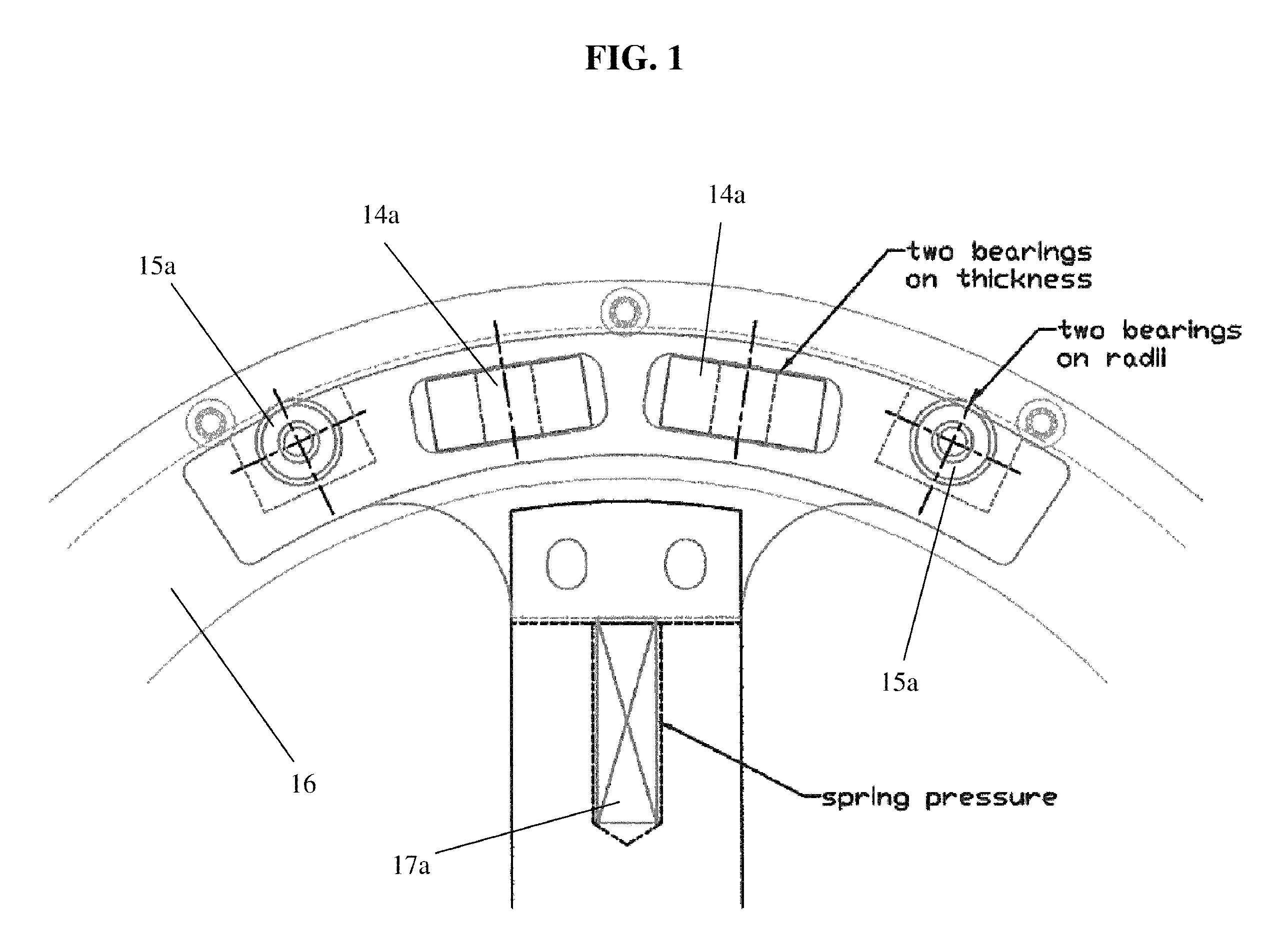
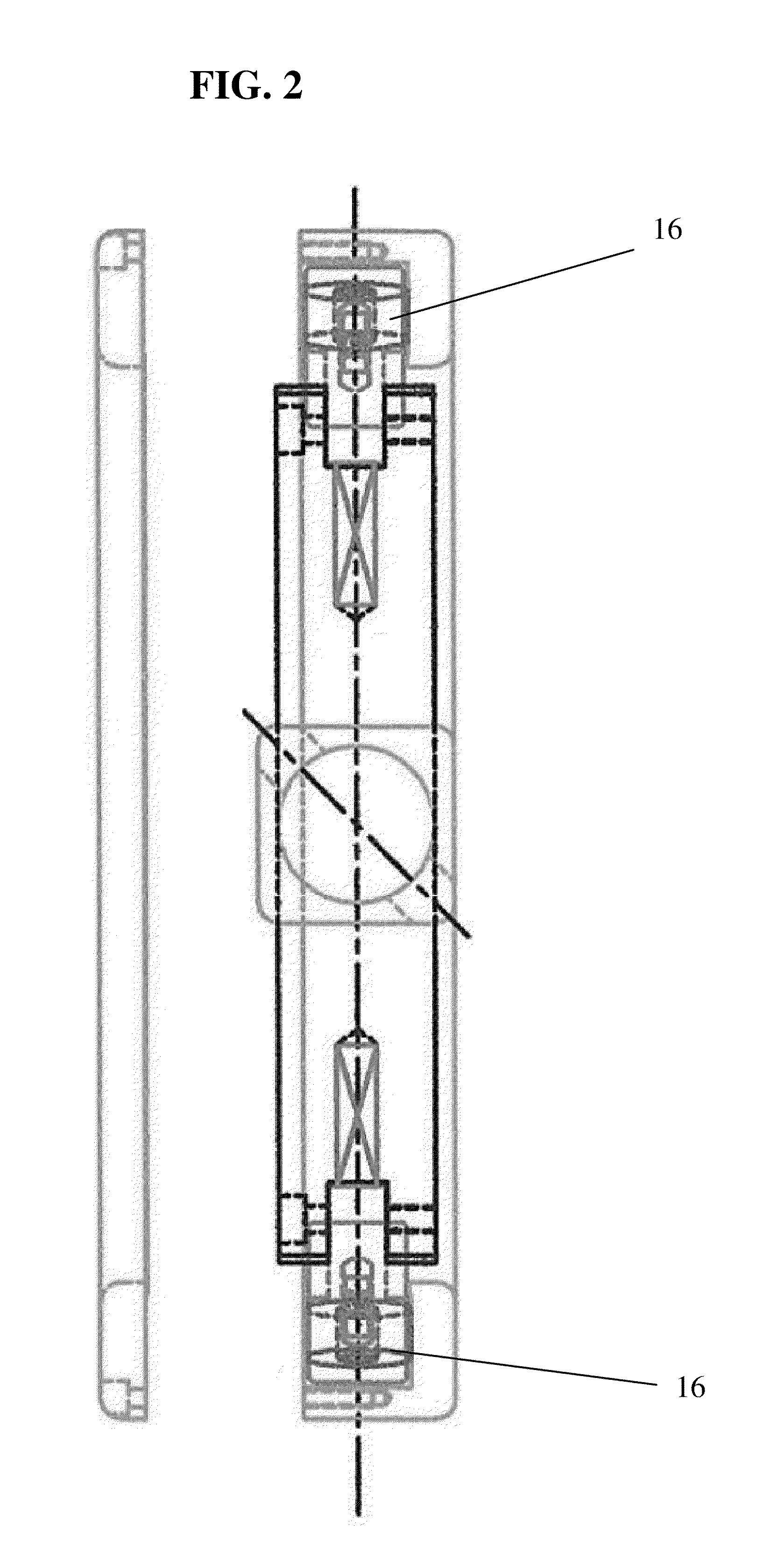
[0028]As depicted in FIGS. 1-4, each grip housing 13a and 13b has an interior circumferential groove 16. Each handgrip 11a and 11b has diametrically opposed radial bearings 15a and 15b that are located wit...


PUM


Abstract

A barbell with rotational grips. The barbell includes a center bar with two grip housings of annular configuration mounted to opposite ends of the barbell. Handgrips are located within the grip housings. Two sets of bearings are diametrically opposed to one another at the ends of each handgrip. A first set of radial wall bearings are perpendicular to the rotational axis of the handgrip, and a second set of sidewall bearings are parallel to the rotational axis of the handgrip. Each grip housing has an interior circumferential groove, with radial and sidewall bearings operatively secured within the groove. Each hand grip is spring-loaded so that a constant force is applied perpendicular to the rotational axis of the handgrips.

Description

BACKGROUND OF THE INVENTION[0001]1. Field of the Invention[0002]This invention relates to a weightlifting apparatus. More particularly, it relates to a weightlifting barbell with rotational grips.[0003]2. Description of the Prior Art[0004]Weightlifting is an increasingly popular form of exercise. In weightlifting, barbells are used to lift and pull various weights. Barbells typically include various types of bars having a bent structure to accommodate a variety of grasping orientations, as disclosed in U.S. Design Pat. No. D287,526.[0005]Weight training exercises can also be performed using dumbbells. Since one dumbbell is held in each hand, a user can freely rotate the wrist and hand throughout the full range of motion as an exercise is performed. For example, in performing a shoulder press with dumbbells, a user holds a dumbbell in each hand directly beside the shoulders, with the palms facing toward each other. Then the dumbbells are raised over the head, and the palms are rotate...

Claims


Application Information

Patent Timeline
Patent Type & Authority Patents(United States)
IPC IPC(8): A63B21/072
CPCA63B21/0724A63B21/075A63B21/1434A63B21/1469A63B21/062A63B21/0628A63B21/4017A63B21/4035
Inventor WATSON, JOSEPH E.
Owner SPINGRIP FITNESS
Why Eureka
Try Eureka