Apparatus and methods for continuous variable valve timing

a technology of continuous variable valve timing and apparatus, which is applied in the direction of valve drive, machine/engine, gear drive, etc., can solve the problems of timing belt failure, ineffective operation, mechanical complexity of phase shift devices,

Inactive Publication Date: 2011-01-11
AES INDS
View PDF89 Cites 14 Cited by
  • Summary
  • Abstract
  • Description
  • Claims
  • Application Information

AI Technical Summary

Problems solved by technology

Some phase shift devices may be mechanically complex.
Other phase shift devices may vary the timing belt path length of the timing belt, which could limit the range over which the phase relationship may be altered, cause the device to bind, cause over-tensioning of the timing belt thereby causing the timing belt to fail, or otherwise function ineffectively.

Method used


Image

  • Apparatus and methods for continuous variable valve timing
  • Apparatus and methods for continuous variable valve timing
  • Apparatus and methods for continuous variable valve timing

Examples


example 1

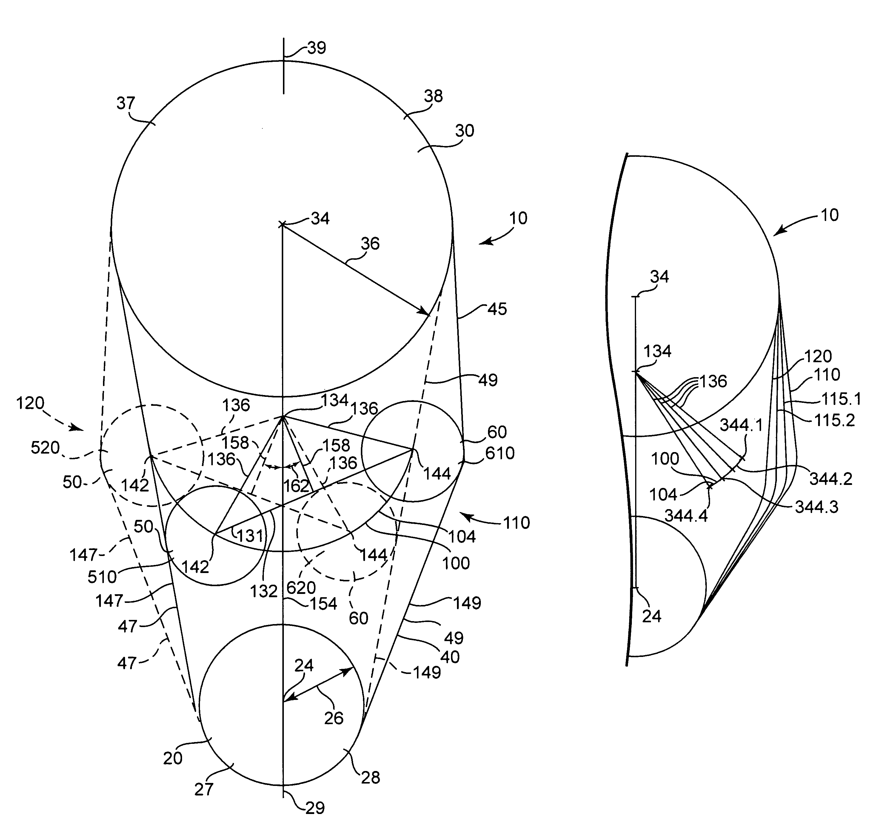
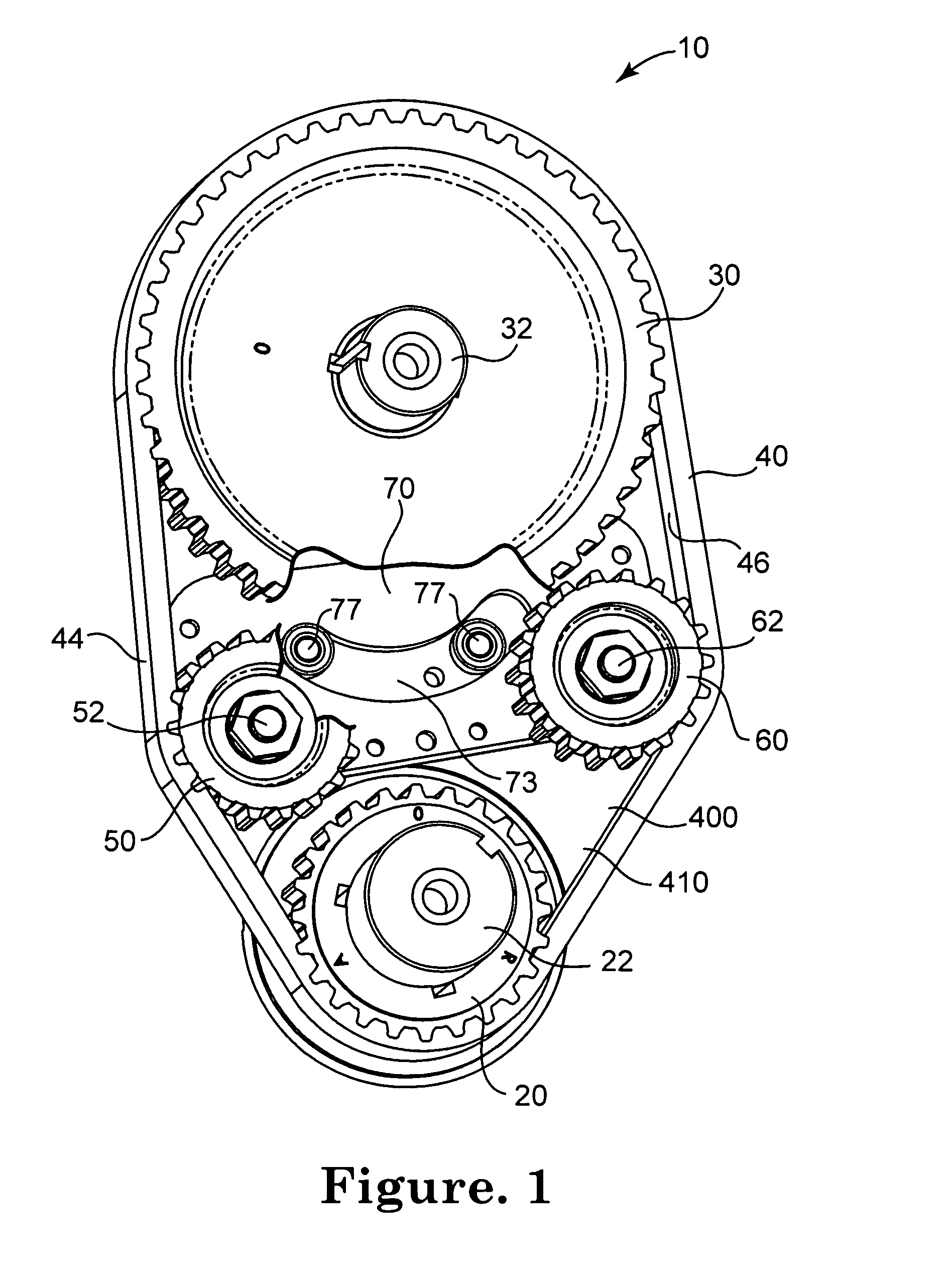
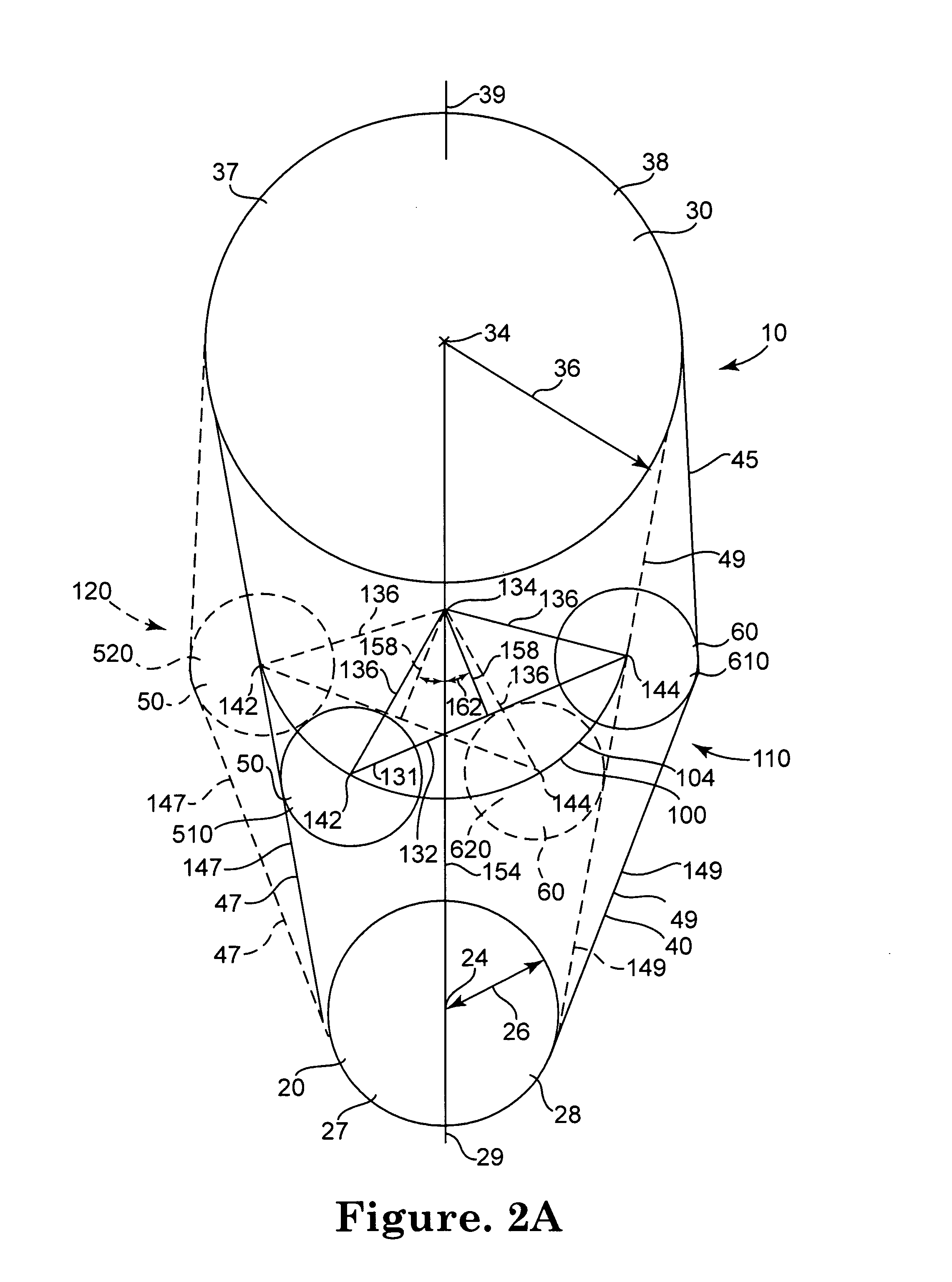
[0052]In Example 1, the configuration of the timing belt 40 was specified as indicated in Table 1-1 and the driver gear 20, the driven gear 30, the first idler 50 and the second idler 60, and the driven gear axis to driver gear axis distance 166 were specified as indicated in Table 1-2. As indicated in Table 1-3, initial values that describe the geometry of the phase shift apparatus 10 were chosen, and these values were refined by iteration subject to the constraints given in Table 1-4. The geometric parameters include the idler center-to-center distance 132, distance of the idler pivot point from driver gear axis 168, the pivot radius 136, and the maximum off-symmetry angle 162. The distance of the idler pivot point from the driver gear axis 168 and the distance of idler pivot point from driven gear axis 169 are illustrated in FIG. 4A. Also illustrated in FIG. 4A is the driven gear axis to driver gear axis distance 166.

[0053]

TABLE 1-1Timing Belt ConfigurationNumber of teeth70Tooth ...

example 2

[0065]In Example 2, the timing belt 40 configuration was specified as indicated in Table 2-1, and the driver gear, the driven gear 30, the first idler 50 and the second idler 60 were specified as indicated in Table 2-2. As indicated in Table 2-3, initial values that describe the geometry of the phase shift apparatus 10 were chosen, and these values were refined by iteration subject to the constraints given in Table 2-4.

[0066]

TABLE 2-1Timing Belt ConfigurationNumber of teeth70Tooth pitch8 mmRadial offset from gear tooth0.02700 in.to belt pitch centerline

[0067]

TABLE 2-2Gear Configurationsnumber of teethDriver Gear24Driven Gear48Idler18Driven gear axis to driver4.968 (in)gear axis distanceOrientationDriver

[0068]

TABLE 2-3Design Optimization ParametersIdler Center-To-Center Distance 3.00 (in)Distance of Idler Pivot Point from driver gear axis 1.20 (in)(Above [+] (Below [−]) (in)Pivot radius 1.60 (in)Maximum Off-symmetry angle12.00 (degrees)

[0069]

TABLE 2-4Optimization ConstraintsMinimum C...


PUM


Abstract

Apparatus and methods for shifting the phase between a driver gear and a driven gear in communication by a timing belt are provided as well as methods for configuring the apparatus. The apparatus may continuously vary the phase relationship between the driver gear and the driven gear.

Description

BACKGROUND[0001]1. Field of the Invention[0002]The present inventions relate to internal combustion engines, and, more particularly, to apparatus and methods for phase shifting a driver gear and a driven gear connected by a timing belt.[0003]2. Description of the Related Art[0004]Various phase shift devices have been developed to alter the phase relationship between a driver gear such as a crankshaft gear and a driven gear such as a driven gear in mechanical communication by a timing belt in an internal combustion engine. Some phase shift devices may be mechanically complex. Other phase shift devices may vary the timing belt path length of the timing belt, which could limit the range over which the phase relationship may be altered, cause the device to bind, cause over-tensioning of the timing belt thereby causing the timing belt to fail, or otherwise function ineffectively. Accordingly, a need exists for improved apparatus and methods for regulating the phase relationship between a...

Claims


Application Information

Patent Timeline
Patent Type & Authority Patents(United States)
IPC IPC(8): F01L1/02
CPCF01L1/02F01L1/024F01L1/348
Inventor LABERE, RIKKI SCOTTWEAVER, ROBERT ALLEN
Owner AES INDS
Why Eureka
Try Eureka