Casing make-up and running tool adapted for fluid and cement control

a technology of fluid and cement control and make-up, applied in the direction of fluid removal, sealing/packing, borehole/well accessories, etc., can solve the problems of unfavorable cement liner quality improvement, well failure, and unfavorable delay

Inactive Publication Date: 2011-01-11
FRANKS INT
View PDF95 Cites 41 Cited by
  • Summary
  • Abstract
  • Description
  • Claims
  • Application Information

AI Technical Summary

Benefits of technology

[0009]The present invention is directed to a method and tool that satisfies the aforementioned and other needs, a casing make-up and running tool adapted for facilitating the intermittent fill up of the casing string and the circulation of fluid in a borehole during and after casing running operations, and for facilitating the lunching of cement wiper plugs and the placement of cement into a targeted interval of the annulus around the string of casing in the borehole.
[0012]In addition to the launcher assembly, the casing make up and running tool of the present invention also comprises a fill up and circulation assembly to provide management and control of fluid in the borehole. In the fill up mode, the fill up and circulation assembly is used to intermittently add fluid to the bore of the casing string to manage the fluid level in the casing string and to prevent unwanted differential pressure (from the annulus into the casing string) that could, if unmanaged, collapse the casing string. In the circulation mode, an elastomer packer element of the fill up and circulation assembly engages the proximal end of the casing string to enable pressurization of the bore of the casing string to force introduced fluid down the bore of the casing string, out of the distal end of the casing string and into the annulus between the casing string and the borehole wall. By recovery of fluid displaced from the annulus at the surface, the fluid may be reconditioned and reused.

Problems solved by technology

Sustained circulation of drilling fluid down the bore of the casing string and back to the surface through the annulus suspends and removes unwanted mud filter cake, drill cuttings and other debris that, if left in the annulus, may compromise the quality of the cement liner and lead to well failure.
Unwanted delays may result from the need for rigging up cement wiper plug launching assemblies or other tools used for cement placement, and from disconnecting fluid lines and connecting cement lines that feed the cement slurry to the bore of the casing string.

Method used


Image

  • Casing make-up and running tool adapted for fluid and cement control
  • Casing make-up and running tool adapted for fluid and cement control
  • Casing make-up and running tool adapted for fluid and cement control

Examples


Embodiment Construction

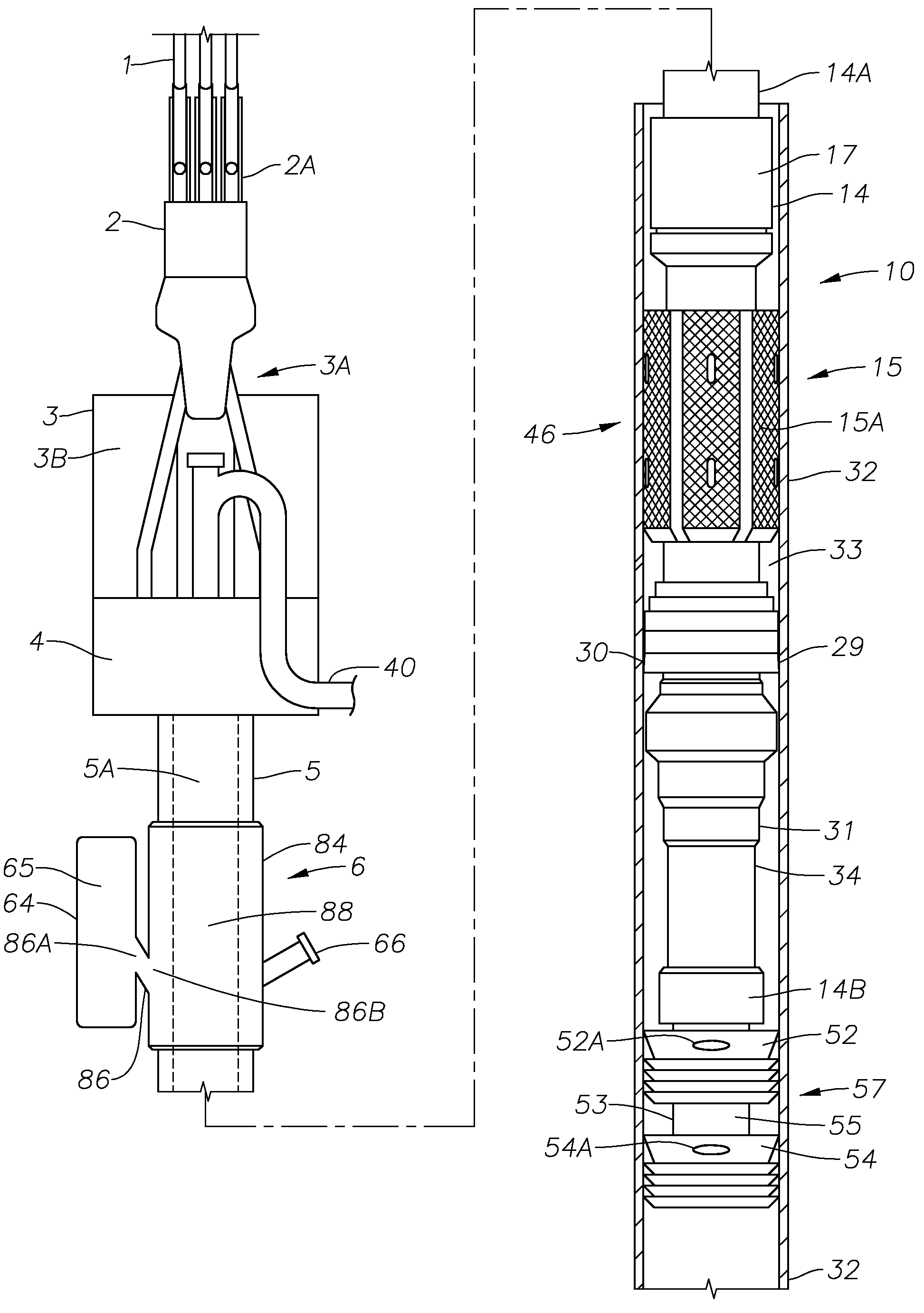
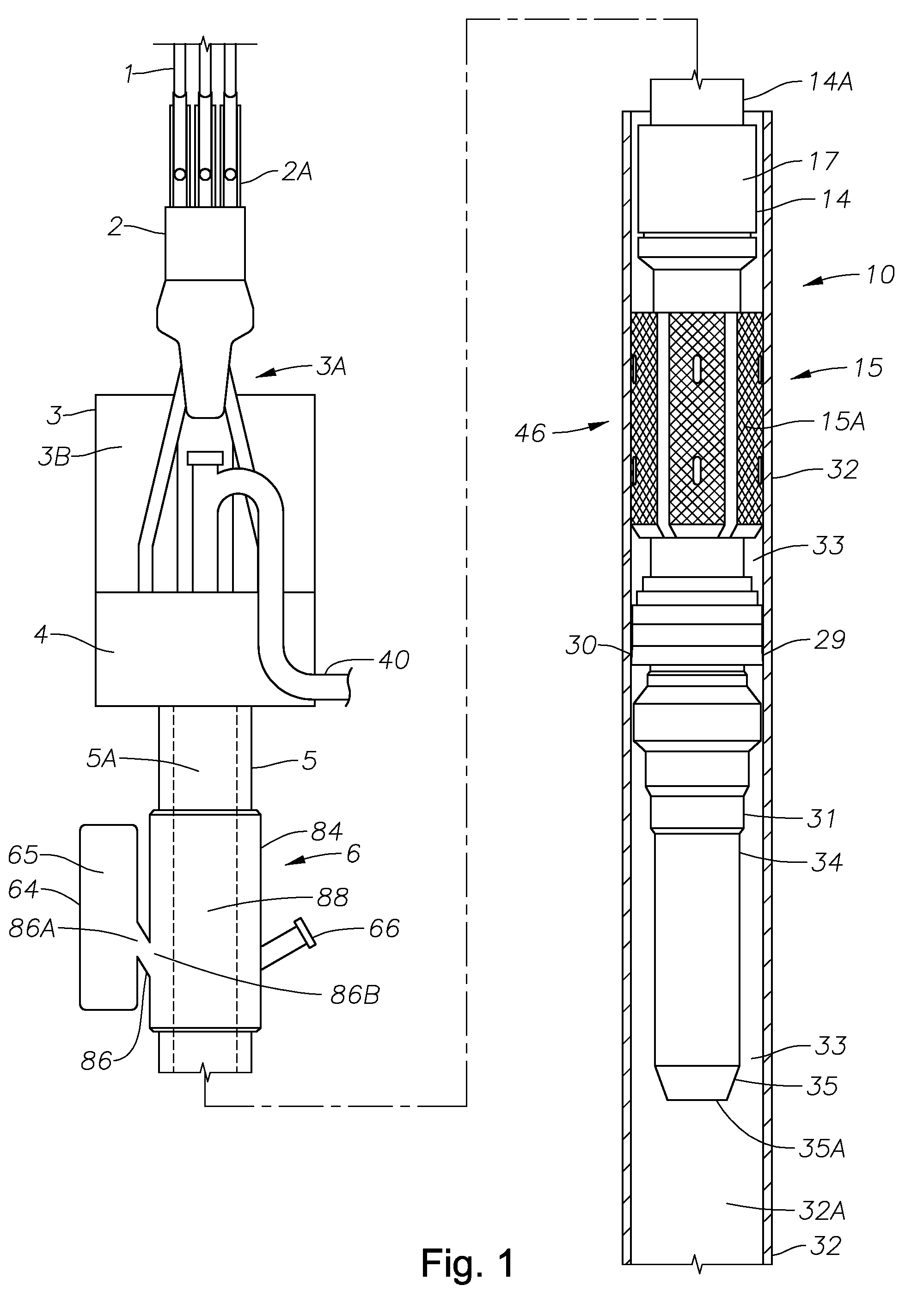
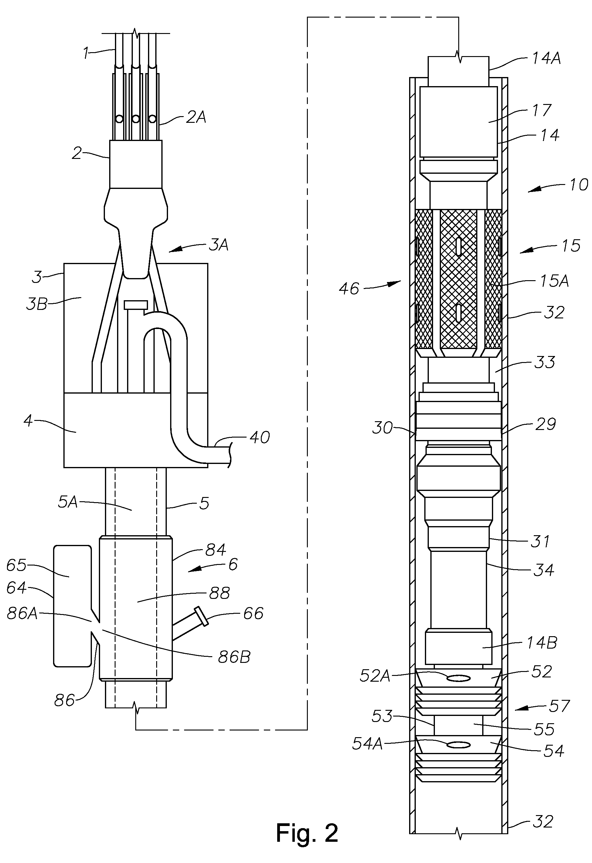
[0019]A string of casing suspended in a borehole may weigh hundreds of thousands of pounds or more, and a robust support structure, such as a derrick, is required to suspend a casing string in the borehole. The casing make-up and running tool of present invention is adapted for being supported above the borehole by a support structure, such as a derrick.

[0020]FIG. 1 is an elevation view of one embodiment of the casing make up and running tool of the present invention comprising a top drive 3 having an upwardly disposed lift eye 3A coupled to and supporting a body 3B and a motor drive assembly 4 secured to the body. The casing make up and running tool is supported by an overhead load-bearing structure (not shown), such as a derrick, that supports a block 2 with a draw works 2A that cooperates with multiple loops of a cable 1. The motor drive assembly 4 of the top drive 3 provides for powered rotation of a generally downwardly disposed drive shaft, or quill 5.

[0021]Fluid flow is provi...


PUM


Abstract

The apparatus of the present invention provides a top drive supported tool for making up and running casing strings into a borehole. The tool comprises a fill-up and circulation assembly and a launcher assembly that is adapted to cooperate with a connectable cement wiper plug assembly for launching wiper plugs that control cement placement in the annulus between a casing string and a borehole containing the casing string. The tool of the present invention shortens or eliminates delays in well operations, thereby improving integrity of cement liners formed by placing cement slurry in a targeted interval.

Description

[0001]This application is a continuation-in-part of U.S. patent application Ser. No. 11 / 512,601 filed on Aug. 29, 2006 now U.S. Pat. No. 7,370,698 which is a continuation of U.S. patent application Ser. No. 10 / 047,727, filed on Jan. 15, 2002 now U.S. Pat. No. 7,096,948 which is a continuation of U.S. patent application Ser. No. 09 / 837,447, filed on Apr. 17, 2001 now abandoned which is a continuation of U.S. patent application Ser. No. 09 / 206,876, filed on Dec. 8, 1998 now U.S. Pat. No. 6,279,654 which was a continuation-in-part of U.S. patent application Ser. No. 08 / 850,496, filed May 2, 1997, now U.S. Pat. No. 5,918,673, which was a continuation-in-part of U.S. patent application Ser. No. 08 / 726,112, filed Oct. 4, 1996, now U.S. Pat. No. 5,735,348.BACKGROUND OF THE INVENTION[0002]1. Field of the Invention[0003]This invention relates to equipment used in the drilling and completion of subterranean wells, and more specifically to equipment used in circulating fluid and in the annular...

Claims


Application Information

Patent Timeline
Patent Type & Authority Patents(United States)
IPC IPC(8): E21B37/04
CPCE21B33/05E21B33/16E21B33/165
Inventor LATIOLAIS, JR., BURNEY J.LUTGRING, KEITH THOMASHAWKINS, III, SAMUEL P.
Owner FRANKS INT
Why Eureka
Try Eureka