Supercharge Your Innovation With Domain-Expert AI Agents!

Complex antenna

a technology of complex antennas and antennas, applied in the direction of resonant antennas, antenna earthings, radiating elements structural forms, etc., can solve the problems of narrow frequency band of band antennas, more and more people dissatisfaction with electronic devices, and the inability to install two sets of antennas in the limited inner space of portable electronic devices, etc., to achieve excellent performance and wide frequency band

Inactive Publication Date: 2011-01-11
HON HAI PRECISION IND CO LTD
View PDF5 Cites 19 Cited by
  • Summary
  • Abstract
  • Description
  • Claims
  • Application Information

AI Technical Summary

Benefits of technology

[0010]An object of the present invention is to provide a complex antenna which has more wider frequency band, and the antenna having the excellent performance. To achieve the aforementioned object, the present invention provides a complex antenna comprising a grounding element, a first antenna, and a second antenna. The grounding element has two longitudinal sides. The first antenna operates in a first wireless network comprising a first radiating body spaced apart from the grounding element and a first connecting element connecting the first radiating body and the grounding element. The second antenna operates in a second wireless network comprising a second body spaced apart from the grounding element and a second connecting element connecting the second radiating body and the grounding element. The first antenna extends from an edge of the grounding element. The first radiating body comprises a first radiating element and a second radiating element. The second antenna extends from another edge of the grounding element. The second radiating body comprises a third radiating element extending from a terminal of the connecting element, a fourth radiating element, and a fifth radiating element extending from a middle portion of the connecting element.

Problems solved by technology

However, more and more people dissatisfy their electronic devices only work in WLAN (Wireless Wide Area Network).
However, with the development of the miniaturization of the portable electronic device, more and more portable electronic devices are difficult to install two sets antennas in the limited inner space.
However, the multi-band antenna has narrow frequency band, and is not capable to cover all frequency bands of WWAN.

Method used


Image

  • Complex antenna
  • Complex antenna
  • Complex antenna

Examples


first embodiment

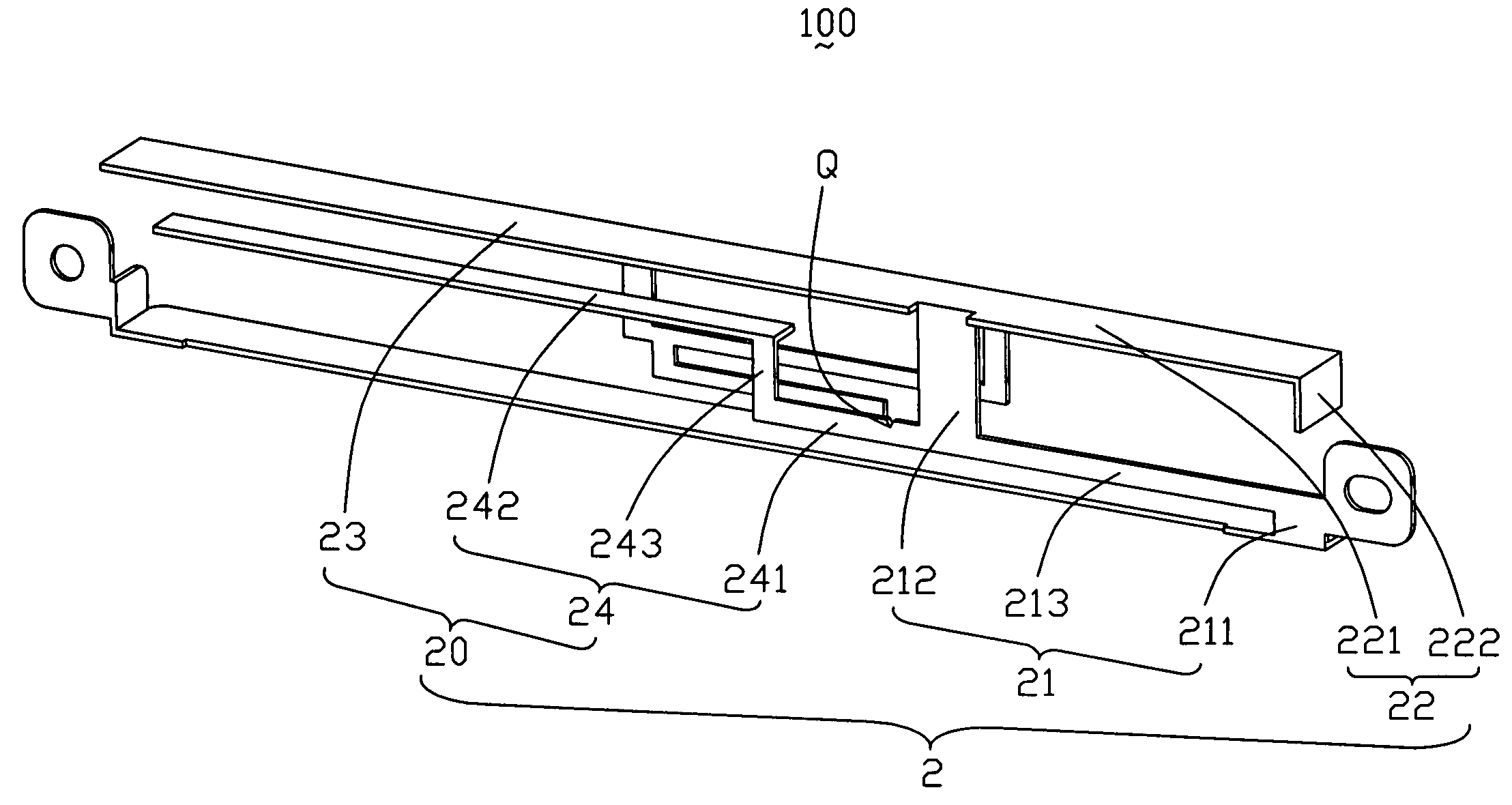
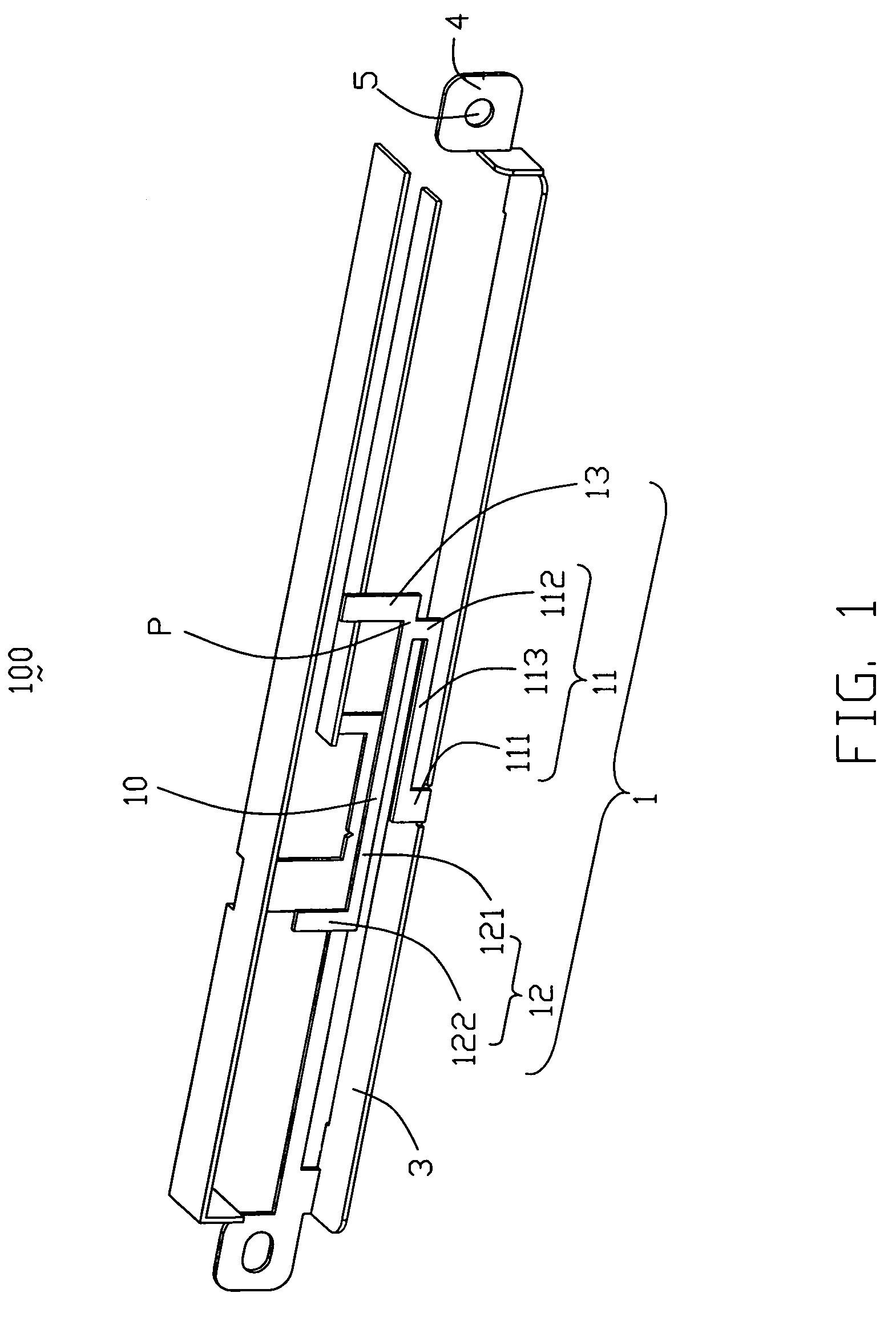
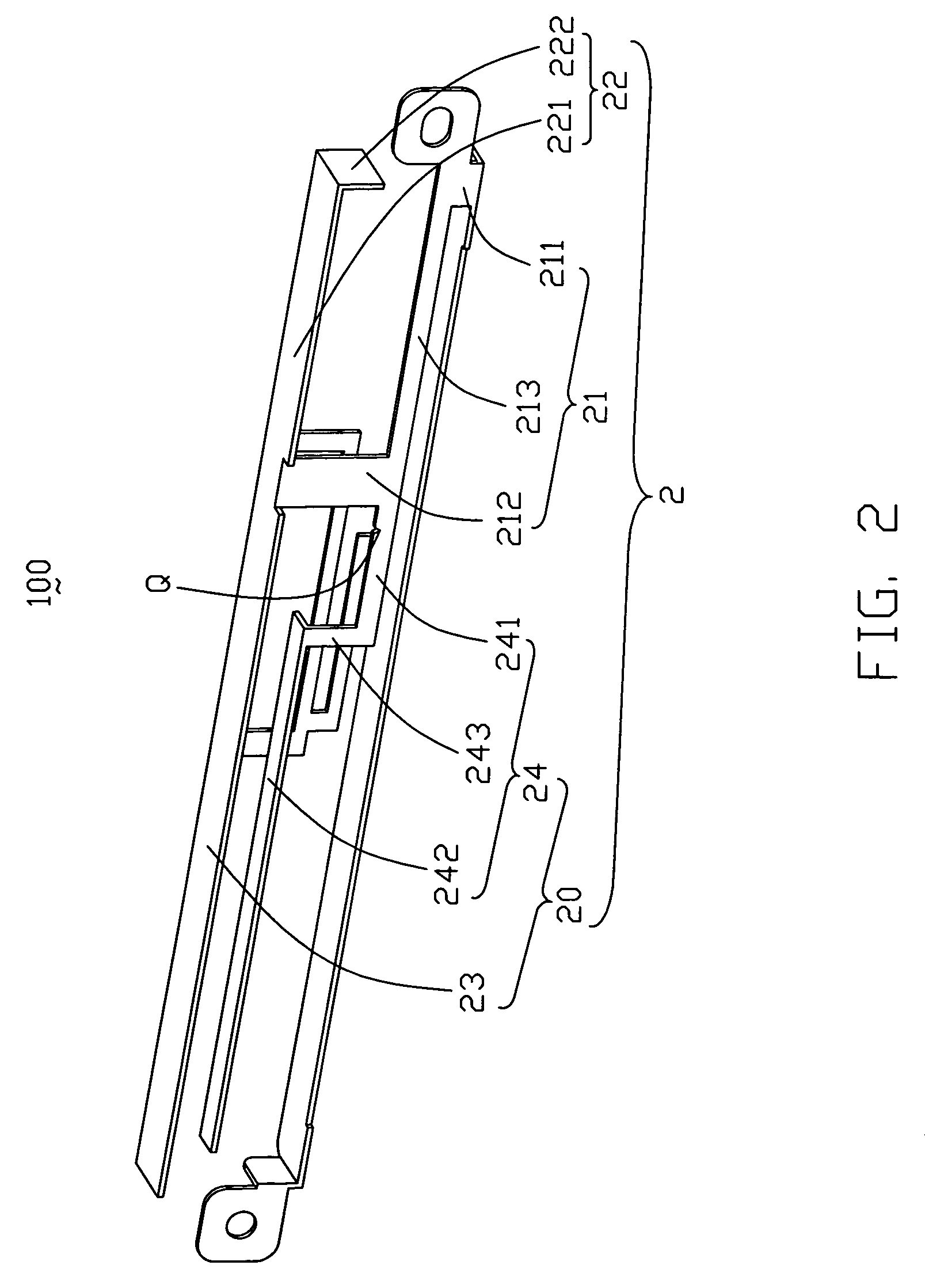
[0022]Referring to FIGS. 1 and 2, a complex antenna 100 in accordance with the present invention comprises a grounding element 3 lying in a horizontal plane and having two longitudinal sides, two installing elements 4 locating respectively at two ends of the grounding element 3, a first antenna 1 and a second antenna 2 extending respectively from two sides of the grounding element 3. The grounding element 3 has a top surface and a bottom surface. All of the first antenna 1, the second antenna 2, and the installing elements 4 locate upside of the top surface of the grounding element 3.

[0023]The first antenna 1 operating in WLAN extends upwardly from middle portion of a first side of the grounding element 3. The first antenna 1 comprises a first radiating body 10 spaced apart from the grounding element 3, a first connecting element 11 in a vertical plane connecting the grounding element 3. The first connecting element 11 comprises a first branch 111 connecting to the grounding element...

second embodiment

[0028]Referring to FIG. 3 and FIG. 4, it's a complex antenna 200 in accordance with the present invention. Basic structure of the complex antenna 200 is approximately same as that of the complex antenna 100. The complex antenna 200 comprises a first antenna 1′ and a second antenna 2′. Description of the different between the complex antenna 200 and the complex antenna 100 is as follows.

[0029]The first antenna 1′ of the complex antenna 200 extends upwardly from a side of the grounding element 3′ comprising a first radiating body 10′ spaced apart from a grounding element 3′ and extending along a longitudinal direction and a first connecting element 11′ lying in a vertical plane and connecting the first radiating body 10′ and the grounding element 3′. The first radiating body 10 comprises a first radiating element 12 operating at 2.4 GHz frequency band and a second radiating element 13 operating at 5 GHz frequency band. A joint P of the first connecting element 11 and the first radiati...

third embodiment

[0031]Referring to FIG. 5 and FIG. 6, it's a complex antenna 300 in accordance with the present invention. Basic structure of the complex antenna 300 is approximately same as that of the complex antenna 100. The complex antenna 300 also comprises a first antenna 1″ and a second antenna 2″. Description of the different between the complex antenna 300 and the complex antenna 100 is as follows.

[0032]The first antenna 1″ of the complex antenna 300 comprises a Z-shaped first radiating element 12″. The second antenna 2″ of the complex 300 is same as the second antenna 2 of the complex antenna 100. The complex antenna 300 comprises an L-shaped coupling radiating element 7″ extending from a side of the grounding element spaced apart a certain distance to the first antenna 1″. A length of the coupling radiating element 7″ is about equal to that of the fourth radiating element 23″. So, the fifth radiating element 24″ can widen the high frequency band of WWAN.


PUM


Abstract

A complex antenna includes a first antenna and a second antenna having a grounding element and an installing element sharing with the first antenna. The first antenna working in a WLAN (Wireless Local Area Network) comprises a first connecting element, a first radiating element and a second radiating element extending from the first connecting element in opposite direction. The second antenna working in a WWAN (Wireless Wide Area Network) comprises a second connecting element and at least three radiating elements extending from the second connecting element in different directions.

Description

BACKGROUND OF THE INVENTION[0001]1. Field of the Invention[0002]The present invention relates generally to an antenna, and more particularly to a complex antenna working in two wireless networks.[0003]2. Description of Prior Art[0004]Wireless communication devices, such as cellular phones, notebook computers, electronic appliances, and the like, are normally equipped with an antenna that serves as a medium for transmission and reception of electromagnetic signals, such as date, audio, image, and so on. However, more and more people dissatisfy their electronic devices only work in WLAN (Wireless Wide Area Network). Making the portable electronic devices working in WWAN (Wireless Wide Area Network) or GPS (Global Positioning System) is a purpose of the many people.[0005]In recent years, WLAN adopts two technical standards of Bluetooth and Wi-Fi. Bluetooth works in 2.4 GHz, and Wi-Fi works in 2.4 GHz and 5 GHz. However, WWAN adopts three technical standards of GSM(Global System for Mob...

Claims


Application Information

Patent Timeline
Patent Type & Authority Patents(United States)
IPC IPC(8): H01Q1/38H01Q5/371H01Q5/40
CPCH01Q9/0421H01Q5/40H01Q5/371H01Q19/005
Inventor HUNG, CHEN-TATAI, LUNG-SHENGSU, WEN-FONG
Owner HON HAI PRECISION IND CO LTD
Features
  • R&D
  • Intellectual Property
  • Life Sciences
  • Materials
  • Tech Scout
  • Unparalleled Data Quality
  • Higher Quality Content
  • 60% Fewer Hallucinations
Learn More