Current-based position sensing

a position sensing and current technology, applied in the field of position sensing, can solve the problems of inability or desirable real-time three-dimensional imaging

Active Publication Date: 2011-01-11
BIOSENSE WEBSTER INC
View PDF31 Cites 327 Cited by
  • Summary
  • Abstract
  • Description
  • Claims
  • Application Information

AI Technical Summary

Problems solved by technology

In most situations, however, real-time three-dimensional imaging is not possible or desirable.

Method used


Image

  • Current-based position sensing
  • Current-based position sensing
  • Current-based position sensing

Examples


Embodiment Construction

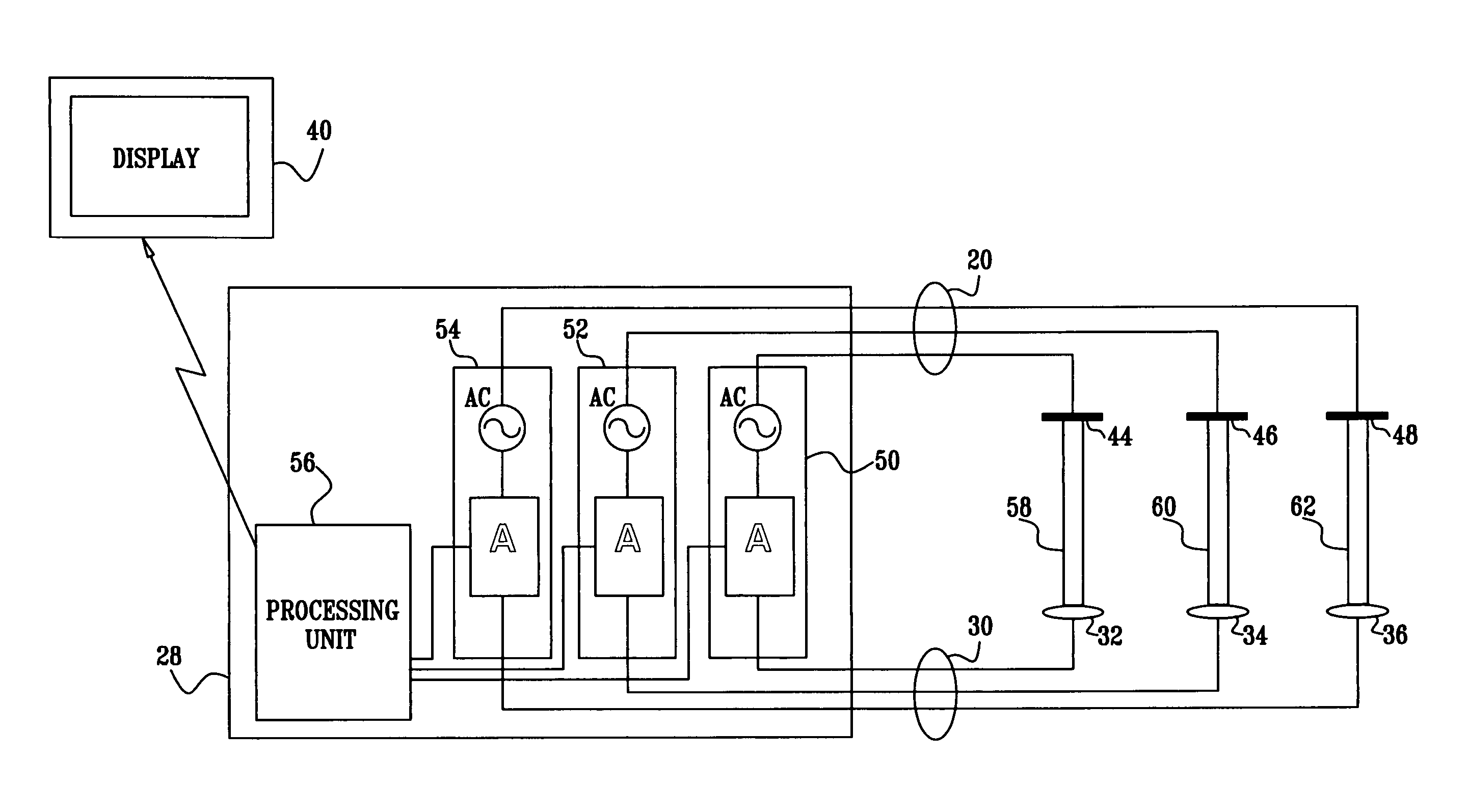
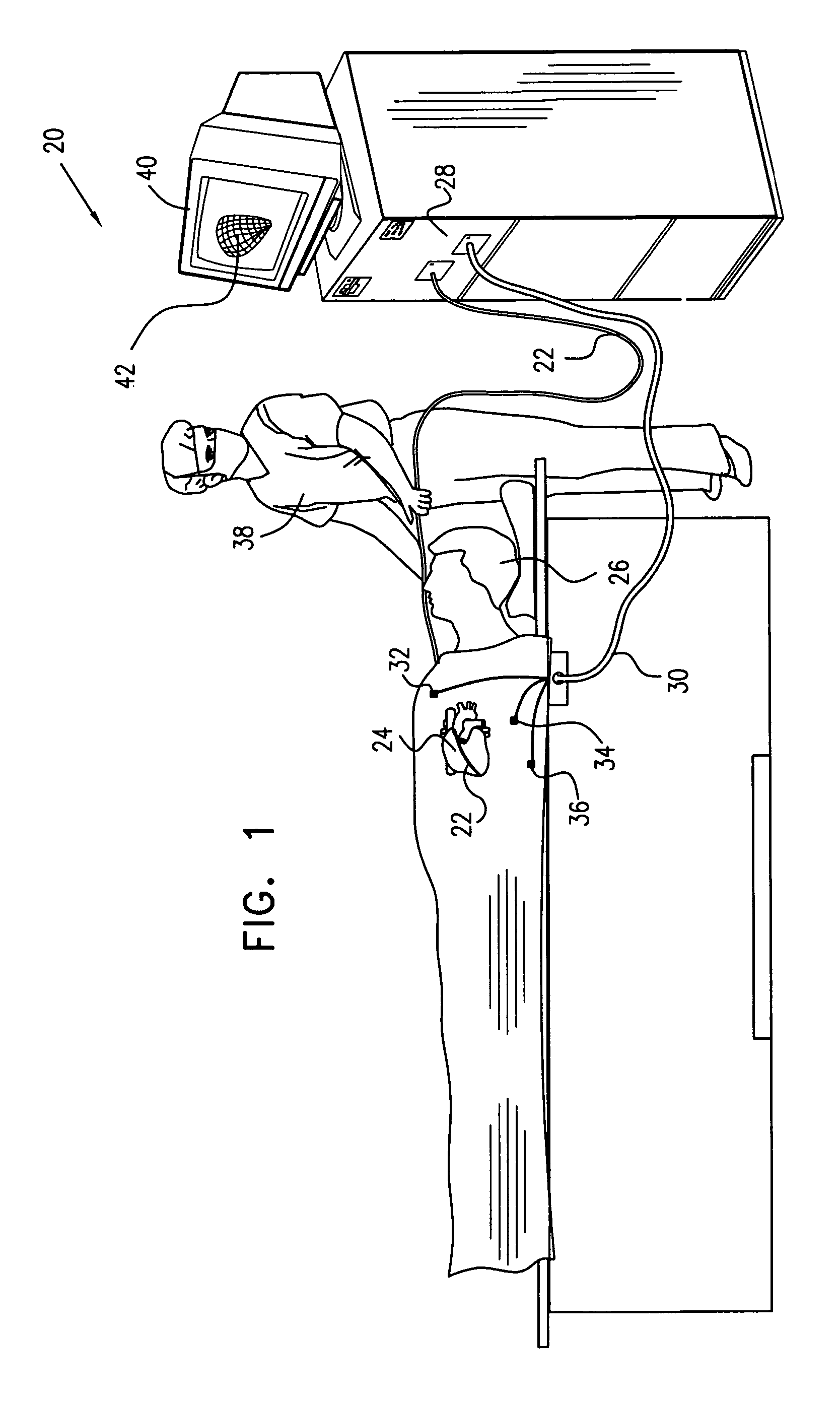
[0025]FIG. 1 is an illustration of a position sensing system 20, in accordance with an embodiment of the present invention. System 20 is used in determining the position of a probe, such as a catheter 22, which is inserted into an internal body cavity, such as a chamber of a heart 24 of a subject 26. Typically, the catheter is used for diagnostic or therapeutic treatment, such as mapping electrical potentials in the heart or performing ablation of heart tissue. The catheter or other intrabody device may alternatively be used for other purposes, by itself or in conjunction with other treatment devices.

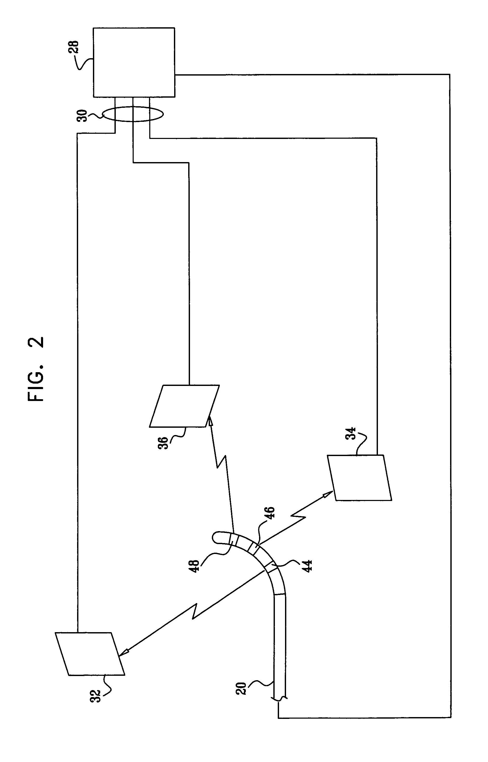
[0026]The distal tip of catheter 22 comprises one or more electrodes (shown below in FIG. 2). These electrodes are connected by wires through the insertion tube of catheter 22 to driver circuitry in a control unit 28, as described below. The control unit is connected by wires through a cable 30 to body surface electrodes, which typically comprise adhesive skin patches 32, 34, and 36. In...


PUM


Abstract

A method for position sensing includes inserting a probe comprising at least one electrode into a body of a subject, and passing electrical currents through the body between the at least one electrode and a plurality of locations on a surface of the body. Respective characteristics of the currents passing through the plurality of the locations are measured in order to determine position coordinates of the probe.

Description

FIELD OF THE INVENTION[0001]The present invention relates generally to sensing the position of an object placed within a living body, and specifically to position sensing using impedance measurements.BACKGROUND OF THE INVENTION[0002]A wide range of medical procedures involve placing objects, such as sensors, tubes, catheters, dispensing devices, and implants, within the body. Real-time imaging methods are often used to assist doctors in visualizing the object and its surroundings during these procedures. In most situations, however, real-time three-dimensional imaging is not possible or desirable. Instead, systems for obtaining real-time spatial coordinates of the internal object are often utilized.[0003]Many such position sensing systems have been developed or envisioned in the prior art. Some systems involve attaching sensors to the internal object in the form of transducers or antennas, which can sense magnetic, electric, or ultrasonic fields generated outside of the body. For ex...

Claims


Application Information

Patent Timeline
Patent Type & Authority Patents(United States)
IPC IPC(8): A61B5/04A61B5/05A61B8/00
CPCA61B5/06A61B5/063A61N1/08A61B2019/5253A61B2034/2053
Inventor GOVARI, ASSAFALTMANN, ANDRES CLAUDIOEPHRATH, YARON
Owner BIOSENSE WEBSTER INC
Why Eureka
Try Eureka