Solenoid actuator and method for making and using same

a solenoid actuator and actuator technology, applied in the direction of magnets, operating means/releasing devices of valves, magnetic bodies, etc., can solve the problems of inability to use automated assembly equipment for assembling, mechanical joints and/or seals between plugs and coil tubes can become compromised, add expense and complexity to the assembly process, etc., to achieve the effect of convenient and less costly assembling

Inactive Publication Date: 2011-01-18
ARMOR MAGNETIC COMPONENTS
View PDF4 Cites 25 Cited by
  • Summary
  • Abstract
  • Description
  • Claims
  • Application Information

AI Technical Summary

Benefits of technology

[0009]The present invention overcomes the shortcomings of the prior art by providing a solenoid actuator having a captive armature. In preferred embodiments, the present invention uses fewer parts than the conventional actuator described above and is easier and less costly to assemble.

Problems solved by technology

Nothing prevents the armature from falling out of the coil tube while assembling the actuator to the valve body or when removing the actuator from the valve body for maintenance, for example, replacement of the valve poppet.
This makes it impractical to use automated assembly equipment for assembling the actuator to the valve body.
Second, the mechanical joint and / or seal between the plug and coil tube can become compromised as a result of the armature hammering against the plug as the actuator is cycled during normal use.
Third, the use of threaded fasteners to secure the frame to the valve body mounting plate adds expense and complexity to the assembly process.
Fourth, such fasteners can back out during operation as a result of vibration, resulting in failure of the actuator and loss of valve function.
This technology suffers from all of the shortcomings described above and the additional shortcoming of a coil tube that is not secured by the frame and, therefore, must be retained by some external means until the actuator is assembled to the valve body.

Method used


Image

  • Solenoid actuator and method for making and using same
  • Solenoid actuator and method for making and using same
  • Solenoid actuator and method for making and using same

Examples


Embodiment Construction

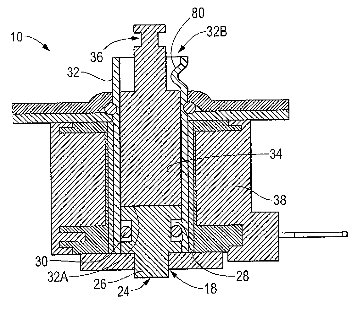
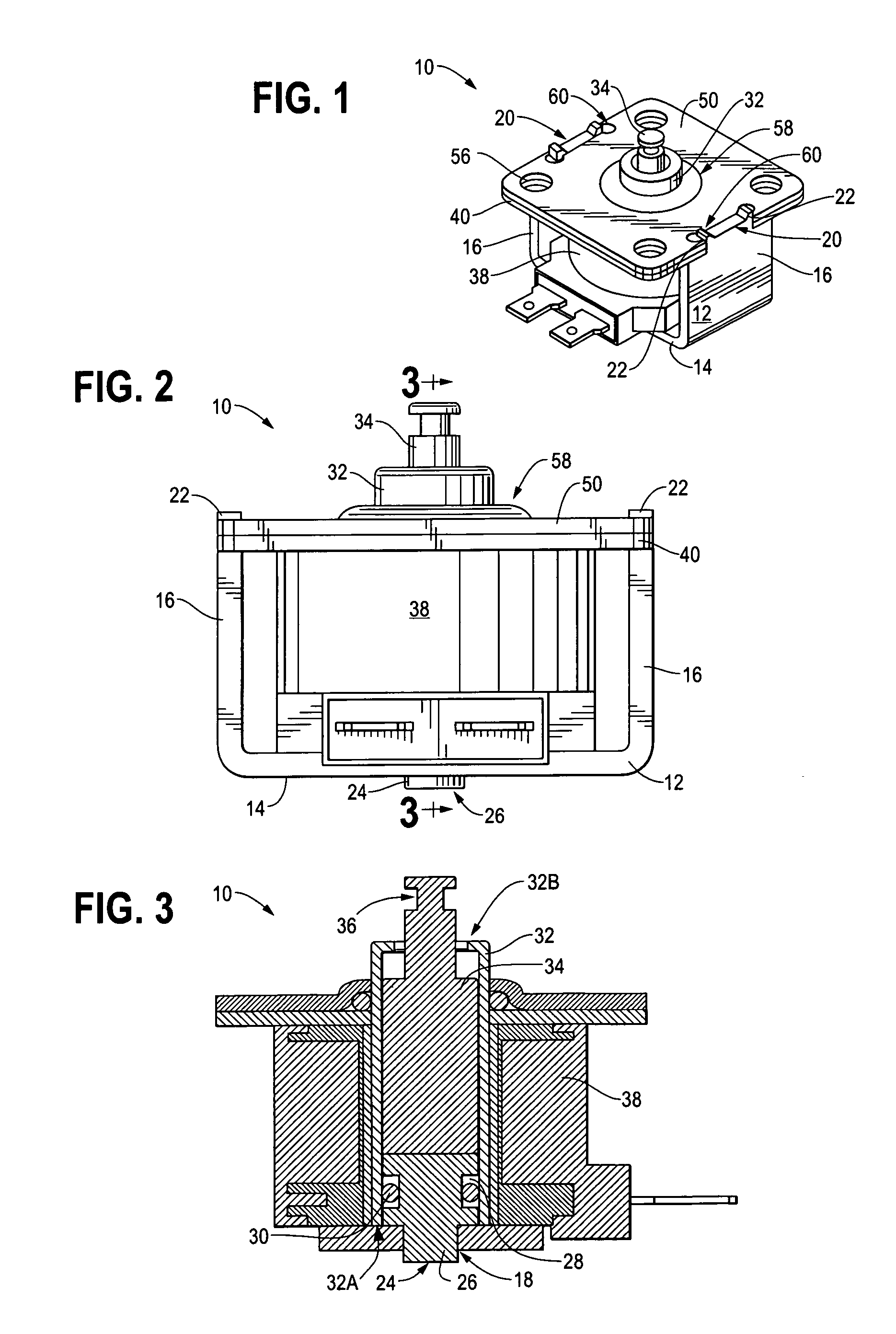
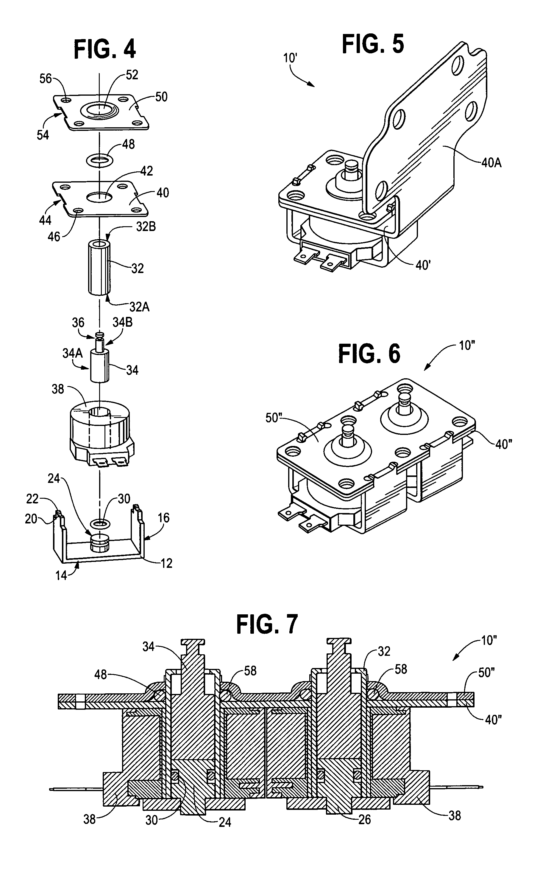
[0021]FIGS. 1-4 illustrate a solenoid actuator 10 according to a preferred embodiment of the present invention. Solenoid actuator 10 includes a frame 12 having a base 14 and two sides 16, each of which is generally perpendicular to base 14. Base 14 preferably includes a locating aperture 18 for receiving nipple 26 of plug 24, as will be discussed further below. In embodiments wherein plug 24 does not include nipple 26, aperture 18 could be omitted from frame 12. A tab 20 preferably projects from an upper edge of each of sides 16 and one or more stakes 22 preferably project from each of tabs 20 for use in securing together the components comprising solenoid actuator 10, as will be discussed further below. Frame 12 can be made of any suitable ferrous or ferromagnetic material, as would be known to one skilled in the art. In a preferred embodiment, frame 12 is a C1010 steel stamping.

[0022]Plug 24 is a generally cylindrical structure attached to base 14 of frame 12. Preferably, plug 24 ...


PUM

PropertyMeasurementUnit
diameteraaaaaaaaaa
ferromagneticaaaaaaaaaa
inner diameteraaaaaaaaaa

Abstract

A solenoid actuator includes a generally cylindrical armature captured to a generally annular coil tube by means of interference geometry. A major portion of the coil tube has a first inside diameter and a second portion of the coil tube has a second, smaller inside diameter. A first portion of the armature has an outside diameter corresponding to the inside diameter of the first portion of the coil tube, and a second portion of the armature has an outside diameter corresponding to the inside diameter of the second portion of the coil tube. The armature is inserted within the coil tube such that the second portion of the armature is free to slide through the second end of the coil tube. A coil tube end closure, for example, a plug, is joined to the first portion of the coil tube. An O-ring provides a seal between the end closure and the tube. A wound electromagnetic coil surrounds the coil tube and can be selectively energized to displace the armature.

Description

CROSS REFERENCE TO RELATED APPLICATIONS[0001]The present application claims priority to, and incorporates by reference the disclosure of, U.S. Provisional Patent Application No. 60 / 716,608, which was filed on Sep. 13, 2005.BACKGROUND OF THE INVENTION[0002]1. The Technical Field[0003]The present invention is directed generally to solenoid actuators and more particularly to a novel solenoid actuator having a captive armature that is especially well-suited for use as a valve actuator in liquid and gas systems.[0004]2. The Related Art[0005]A conventional solenoid actuator typically includes a ferrous plug attached to one end of a non-ferrous coil tube by conventional means, for example, welding, gluing, roll-forming, or crimping. Depending on the attachment method used, an O-ring may be provided to form a seal between the plug and coil tube. The other end of the coil tube is assembled to a valve body mounting plate in a manner that effects a seal between the coil tube and mounting plate...

Claims


Application Information

Patent Timeline
Patent Type & Authority Patents(United States)
IPC IPC(8): H01F3/00F16K31/02
CPCF16K31/0675H01F7/081H01F7/1607H01F7/121H01F7/126H01F7/127H01F7/129H01F2007/083H01F2007/163Y10T137/86622
Inventor ARMOUR, JOHN
Owner ARMOR MAGNETIC COMPONENTS
Why Eureka
Try Eureka