
Galvannealed steel forms

a technology of galvanized steel and forms, applied in the field of forms, can solve the problems of affecting the use of galvanized steel, its inherent susceptibility to corrosion and rusting over a relatively short period, and costs 4 to 5 times as much as comparable carbon steel forms, and achieves the effect of simplifying wall member joints and simplified wall member joints

Active Publication Date: 2011-08-04
RIVERSIDE STEEL
View PDF23 Cites 3 Cited by
  • Summary
  • Abstract
  • Description
  • Claims
  • Application Information

AI Technical Summary

Benefits of technology

The solution reduces assembly time and costs, provides a durable and corrosion-resistant form with a uniform surface, and allows for rapid site-leveling, addressing the limitations of carbon steel and hot dipped galvanized forms.

Problems solved by technology

One long-standing objection to the use of this material is its inherent susceptibility to corrosion and rusting over a relatively short period.
Stainless steel retains its integrity and appearance over an extended period of time, but typically costs 4 to 5 times as much as comparable carbon steel forms.
Hot dipped galvanized forms can have double the life of a painted carbon steel form, but there are manufacturing and finishing issues that add extra costs to this process.
The added manufacturing costs arise from the additional handling required to have the forms hot dipped after fabrication.
The added finishing costs arise out of the fact that a hot dipped surface is not easily painted.
The purpose of the galvanizing zinc coating is to provide excellent protection against corrosion of the base steel, but the coating is not intended to withstand outdoor exposure without chemical treatment or painting.
These additional costs result in a final installed price that is very close to that of stainless steel.
Furthermore, hot dipped forms produce a final form that has an uneven surface and appearance.
That is because the hot dipped process galvanizing material the steel sections are dipped into does not evenly coat each section.
The alignment process during the assembly of such a concrete form can be labor intensive and therefore costly because the labor to align the nuts and bolts and associated brackets during the assembly process can often at times exceed the cost of the material to construct the form.

Method used


Image

  • Galvannealed steel forms
  • Galvannealed steel forms
  • Galvannealed steel forms

Examples


Embodiment Construction

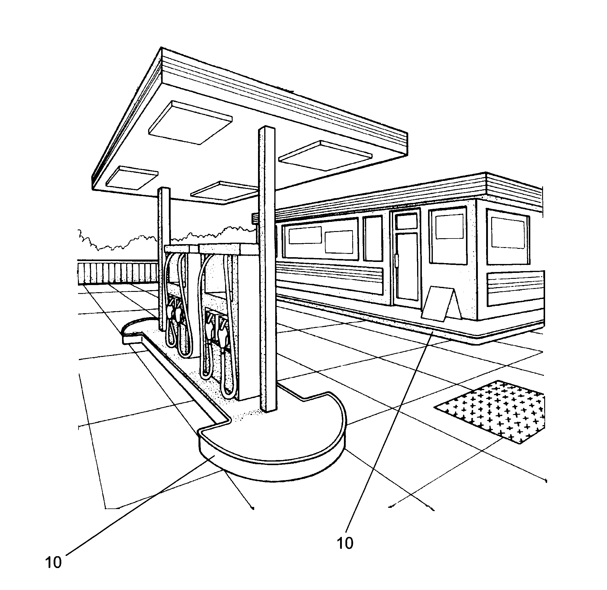
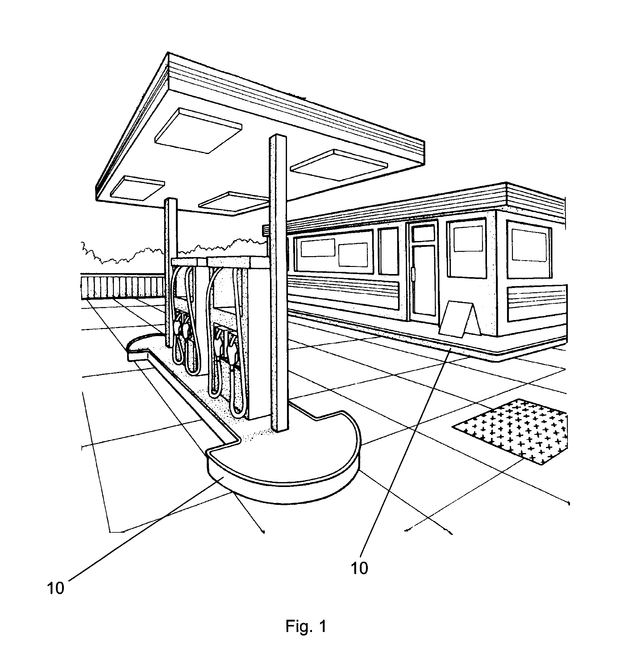
[0032]Referring now to FIG. 1, an example embodiment of a liquid pouring form 10 is shown in use as a pump island form for a gas station. Also shown in FIG. 1 the liquid pouring form 10 is may be used to form a curb or sidewalk around the gas station attendant structure. While the use of the pouring form 10 has been shown as a pump island and a curb, these are example embodiments only. The pouring form can be used anywhere liquids or fill materials such as concrete are used, for example, driveway forms, deck forms, road curb forms, other island structures for ATMs at banks, light pole islands, drive-in restaurant forms and islands, parking garage forms and islands, and the like. The filler material in the island or behind the forms could be any liquid such as liquid concrete, plastics, gels, slurry, building materials, epoxies and any other suitable filler material.

[0033]The example embodiment of FIG. 1 shows a pump island with both curved and straight wall members forming the pouri...


PUM


Abstract

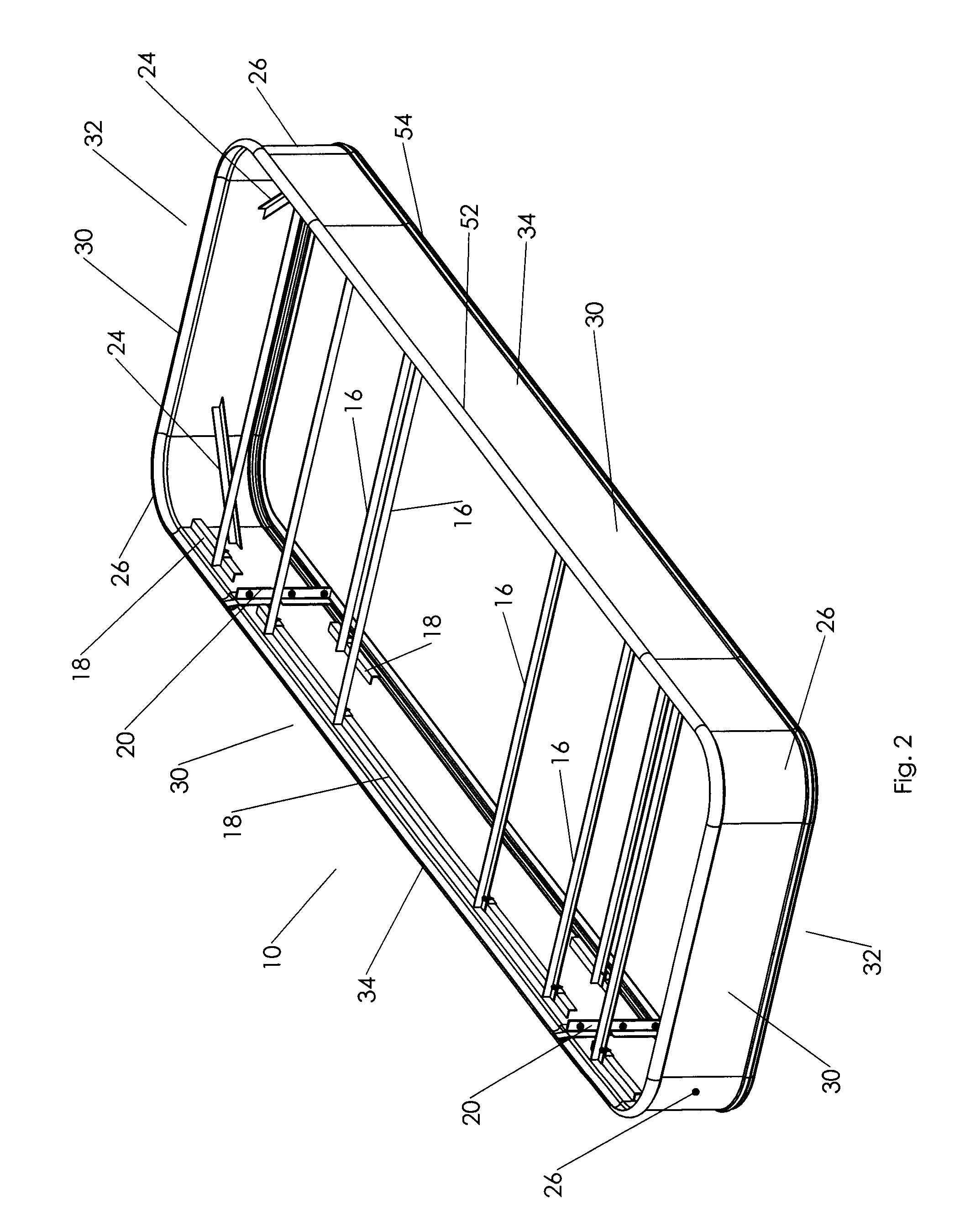
A form for receiving a filler material to create an island is provided. The form is made essentially entirely out of galvannealed steel that is easily paintable. The form has a substantially continuous wall having an outer surface and an inner surface. The wall is made out of a plurality of galvannealed steel wall sections. The wall has a first side and a second side opposite the first side. The inner surface forms an enclosed chamber for receiving the filler material. A first support made out of galvannealed steel is attached to the inner surface of the first side of the wall and a second support made out of galvannealed steel is attached to the inner surface of the second side of the wall. A brace made out of galvannealed steel is disposed between the supports, wherein the brace removably engages the supports.

Description

TECHNICAL FIELD[0001]This invention is related to forms to receive and retain liquid filling material used in construction projects. Specifically this invention relates to a form for pouring concrete for islands that are readily paintable, corrosion resistant, and that can be easily assembled and leveled at the job site and be used to support fuel dispensers, ATM machines, pole bases, walkways, handicap ramps, building and kiosk forms, among others.BACKGROUND ART[0002]Currently, a form for pouring a concrete structure such as an island for fuel dispensing is constructed by aligning a plurality of sheet metal members in an arrangement to define an enclosure. These members then become a permanent part of the concrete structure they retain. The sheet metal commonly used is a 12Ga. carbon steel that is fabricated then prime painted by the manufacturer. A finish coat of paint is applied to the primed metal form after construction is complete and the fuel dispensers are set. This finish c...

Claims


Application Information

Patent Timeline
Patent Type & Authority Applications(United States)
IPC IPC(8): E01C19/50B23P11/00B23P17/00
CPCE01F1/00Y10T29/49826Y10T403/587Y10T29/49963Y10T29/49986F16B2200/71
Inventor RADU, JR., JOHN
Owner RIVERSIDE STEEL
Learn More