
Printing method for reducing stitch error between overlapping jetting modules

Active Publication Date: 2011-01-18
EASTMAN KODAK CO
View PDF14 Cites 47 Cited by
  • Summary
  • Abstract
  • Description
  • Claims
  • Application Information

AI Technical Summary

Benefits of technology

[0018]The technical advantage of the invention is that it enables stitch error corrections to dynamically change during a production run based on an attribute, such as density, of the image data. Stitch artifacts corrected across a stitch joint according to prior procedures sometimes show highlights corrected but dark regions misaligned, or other times show dark regions corrected but highlights misaligned. The invention advantageously provides a uniform correction across the stitch joint where darker regions may need more correction than highlight regions, and vice versa. Furthermore, by making the sub-pixel correction a proportion of the data raster printed by another nearby nozzle, the distribution of data in the highlights is improved and a more uniform correction throughout the tone scale of the image being printed can be obtained.

Problems solved by technology

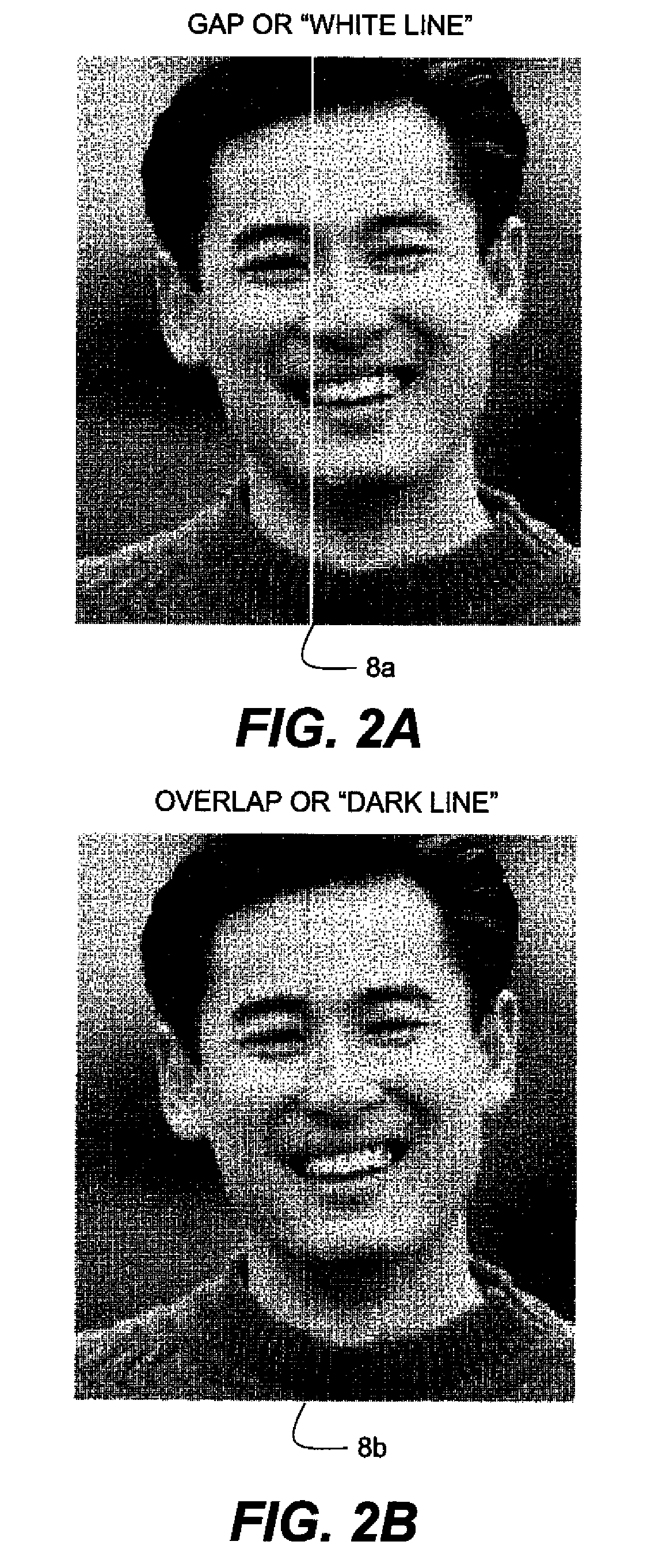
The applicant has observed that the correction amount obtained during a set-up procedure may not be suitable for all image content in a page-width printer, despite the same degree of misalignment of the jetting modules.
In particular, the applicant has observed that the correction amount obtained during a set-up procedure may not be suitable for all density levels in the image.

Method used


Image

  • Printing method for reducing stitch error between overlapping jetting modules
  • Printing method for reducing stitch error between overlapping jetting modules
  • Printing method for reducing stitch error between overlapping jetting modules

Examples


Embodiment Construction

[0042]Because printing systems employing stitching methods are well known, the present description will be directed in particular to elements forming part of, or cooperating more directly with, methods in accordance with the present invention. Elements useful in practicing the methods but not specifically shown or described herein may be selected from those known in the art. Certain aspects of the embodiments to be described may be provided in software. Given an understanding of the system as shown and described according to the invention in the following materials, software not specifically shown, described or suggested herein that is useful for implementation of the invention is conventional and within the ordinary skill in such arts.

[0043]FIG. 3 shows an embodiment of a printer 10 incorporating the invention. In the embodiment of FIG. 3, the printer 10 comprises a housing 12 having a line head 14 that applies markings or otherwise forms an image on a receiver medium 16. The line ...


PUM


Abstract

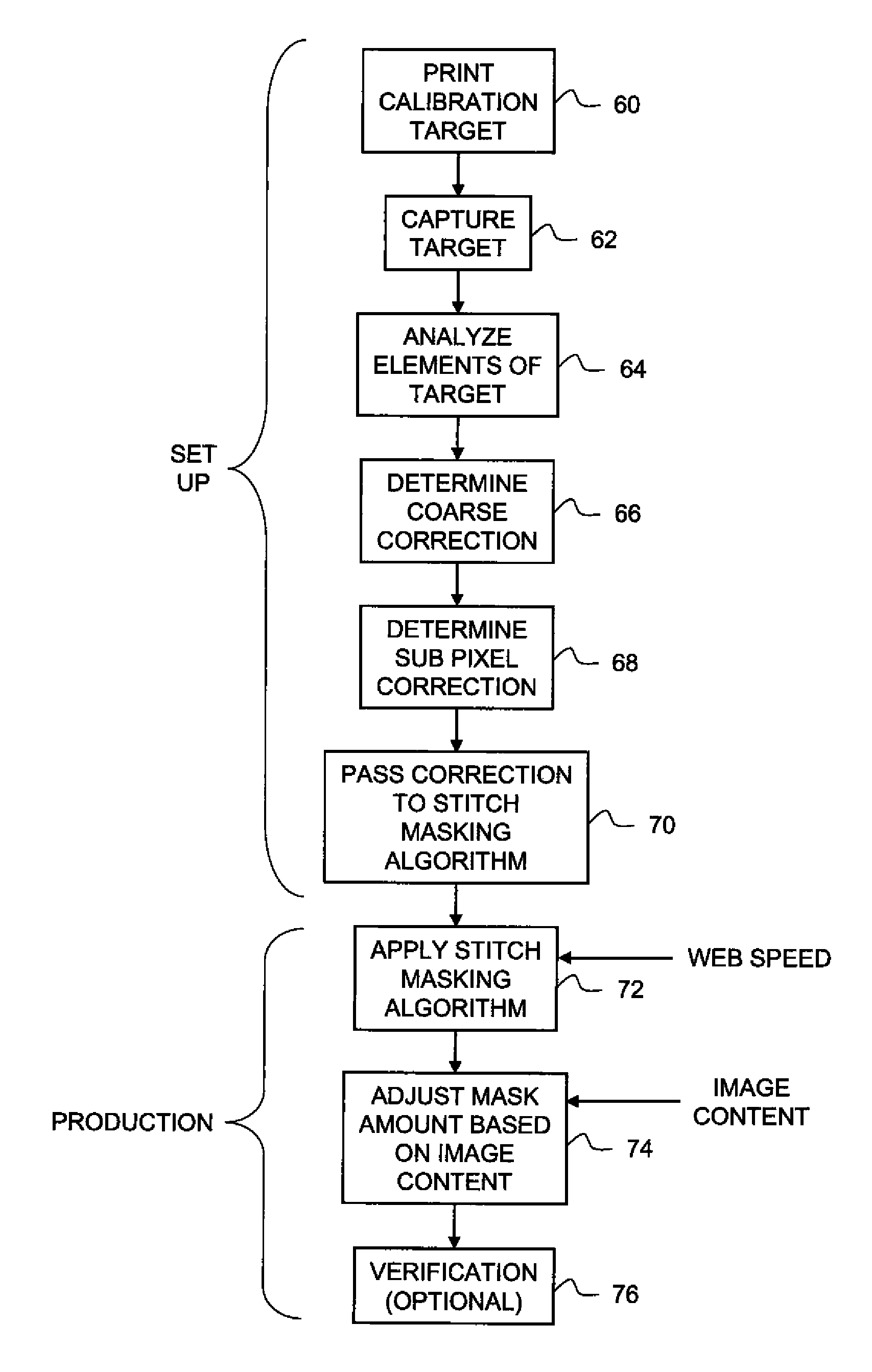
A method of printing is described for a page-width printer including a line head having a plurality of jetting modules that are staggered in a page-width direction. In a set up procedure, a test pattern is printed using the nozzles of adjacent jetting modules, and the pattern is analyzed to detect a stitch error in the overlap regions. The results of this analysis is used to calculate a set of correction values to be applied to print data subsequently sent to nozzles of the adjacent jetting modules to make a correction for the stitch error. During a subsequent production run, the print data sent to the nozzles of the adjacent jetting modules is analyzed to sense an image content attribute, such as gray or density level, of the print data. These results of the analysis of the print data is then used to calculate a dynamic adjustment that is used to adjust the set of correction values calculated during the set up procedure. The line head is then used to print the corrected print data by applying the set of adjusted correction values to production print data subsequently sent to the jetting modules.

Description

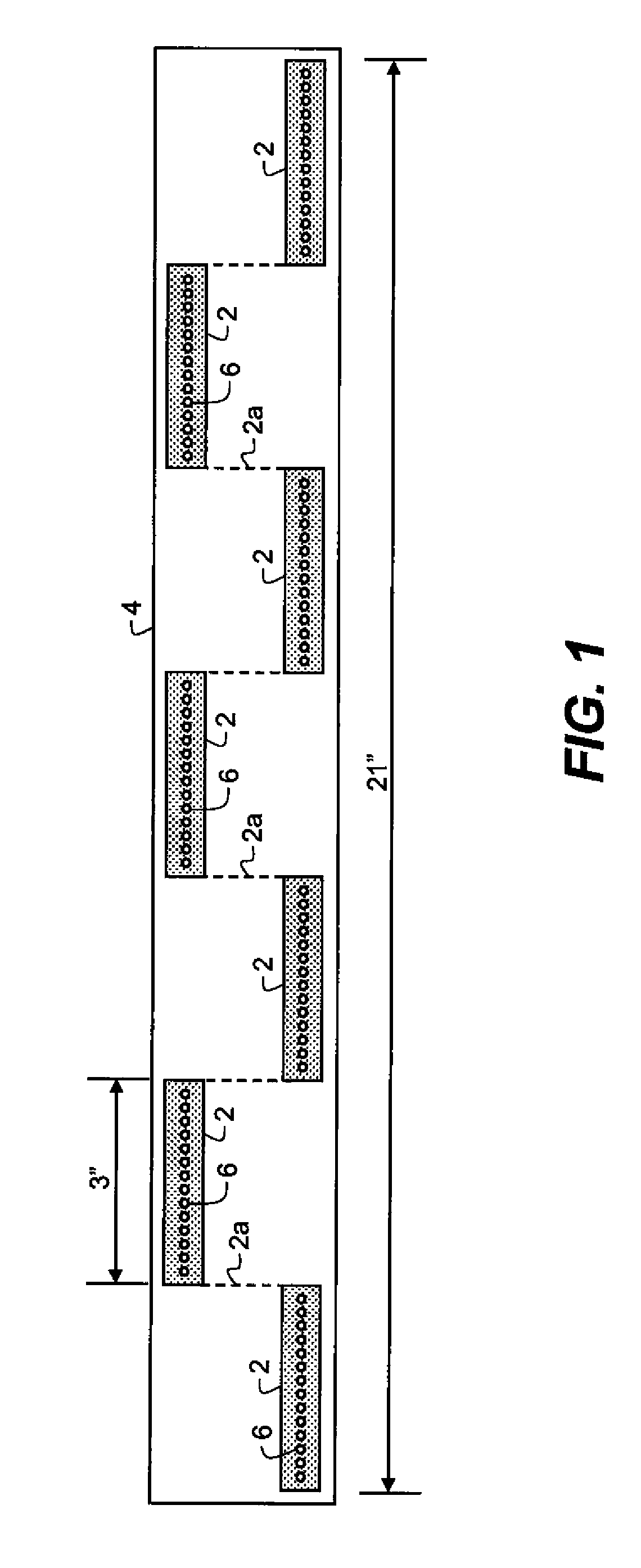
FIELD OF THE INVENTION[0001]The field of the invention relates to page-width printing systems using a line head including a plurality of jetting modules that are staggered in the page-width direction, and more particularly to methods and algorithms for joining the data from the jetting modules in the page-width direction.BACKGROUND OF THE INVENTION[0002]Stitching refers to the alignment of the print from multiple jetting modules for the purpose of creating the appearance of a single page-width line head. For example, as shown in FIG. 1, seven jetting modules 2—each three inches in length—can be stitched together at junctures 2a to form a twenty-one inch page-width line head 4. The page-width image data is processed and segmented into separate segments for each jetting module 2, and then a segment is sent—with an appropriate module-to-module delay to account for the staggered separation of the modules—to the print nozzles 6 of each jetting module for printing.[0003]However, though it...

Claims


Application Information

Patent Timeline
IPC IPC(8): B41J29/393
CPCB41J2/2135G06K15/105G06K15/107G06K2215/111
Inventor ENGE, JAMES M.
Owner EASTMAN KODAK CO
Learn More