Electrocoagulation reactor and water treatment system and method

a technology of electrocoagulation reactor and water treatment system, which is applied in the direction of electrolysis components, filtration, manufacturing tools, etc., can solve the problems of increasing the number of electrode plates, introducing significant complexities, and introducing additional complexities, etc., and achieves convenient design, large electrode surface area, and easy design

Inactive Publication Date: 2009-01-08
POWELL WATER SYST
View PDF3 Cites 17 Cited by
  • Summary
  • Abstract
  • Description
  • Claims
  • Application Information

AI Technical Summary

Benefits of technology

[0008]The spirally wound assembly used in the electrocoagulation reactors of the invention can advantageously be configured generally in a cylindrical shape that can easily be inserted into and retained within a tubular section of a reactor housing. Because of the spirally wound packing of the electrode sheets, a large electrode surface area is obtainable using only two powered electrodes, although use of a greater number of powered electrodes is possible if desired for a particular application. Also, because the separation distance between the powered electrode sheets can be kept small without the need to make a lot of electrical connections, the reactor can be readily designed for operation at lower voltages for many applications. The electrocoagulation reactor, and the spirally wound assembly, may be operated using AC or DC electrical power, but more often is operated using DC electrical power, and often in a range of 1.5 DC volts to 48 volts DC.
[0009]Advantageously, in a preferred design the spirally wound assembly can be configured to fit into and efficiently use the space available in a tubular section of a reactor housing. This is possible because spiral winding is well adapted to making a spirally wound assembly that is generally of cylindrical shape, which can be closely fitted into a tubular housing section to efficiently use available internal reactor volume. Also, because all of the electrode surface area needed for the electrocoagulation reaction is contained within the spirally wound structure, the manufacture and maintenance of the electrocoagulation reactor is not particularly complex. Also, changing electrodes as they are depleted can be accomplished relatively easily by opening the reactor housing, removing the old spirally wound assembly, inserting the new spirally wound assembly, replacing any retaining or sealing pieces as needed, and closing the reactor housing. Also, with a tubular design, the electrocoagulation reactor can often be constructed of generally available components, and without significant mechanical complexity. Additionally, such tubular-based reactors are easily manifolded into a bank of multiple reactors for parallel or series processing through the multiple reactors. For example, additional reactors can easily be added in parallel to increase throughput capacity, or additional reactors can easily be added in series to provide for added reactor length, such as for longer reaction times. Because of the modular design, systems can be accurately scaled up from bench scale to application scale. Usually electrocoagulation systems are piloted on a specific water to determine the efficacy of the process and predict the cost. Multiple modules perform the same as opposed to single reactors with different size and numbers of plates than pilot. Also use of a single set of electrodes aids in accurate scaling. Amps per unit area of electrode surface remains consistent on a given water supply.

Problems solved by technology

The inclusion of a large number of electrode plates, however, introduces significant complexities.
Additional complexities may also be introduced due to the large number of electrical connections that may be required by the use of a large number of electrode plates.
The complexity involved with providing electrical power connections to each of the many electrode plates is significant.
Reactors of this design reduce the number of electrical connections that need to be made, but may have an additional problem relating to the larger separation distance between powered electrode plates that results from inserting the intermediate plates.
However, providing the higher DC voltages that may be used in these reactor designs results in more watts of AC power usage.

Method used


Image

  • Electrocoagulation reactor and water treatment system and method
  • Electrocoagulation reactor and water treatment system and method
  • Electrocoagulation reactor and water treatment system and method

Examples


Embodiment Construction

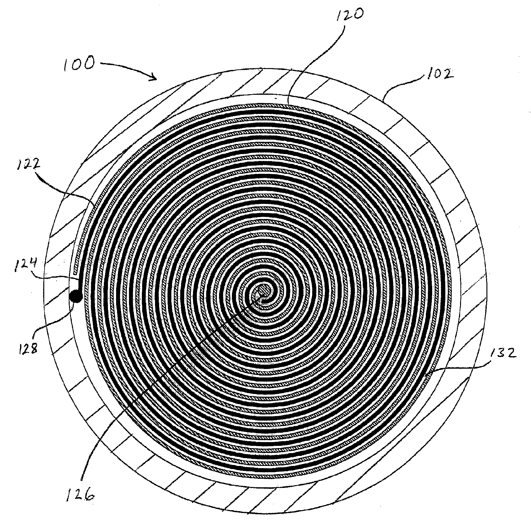
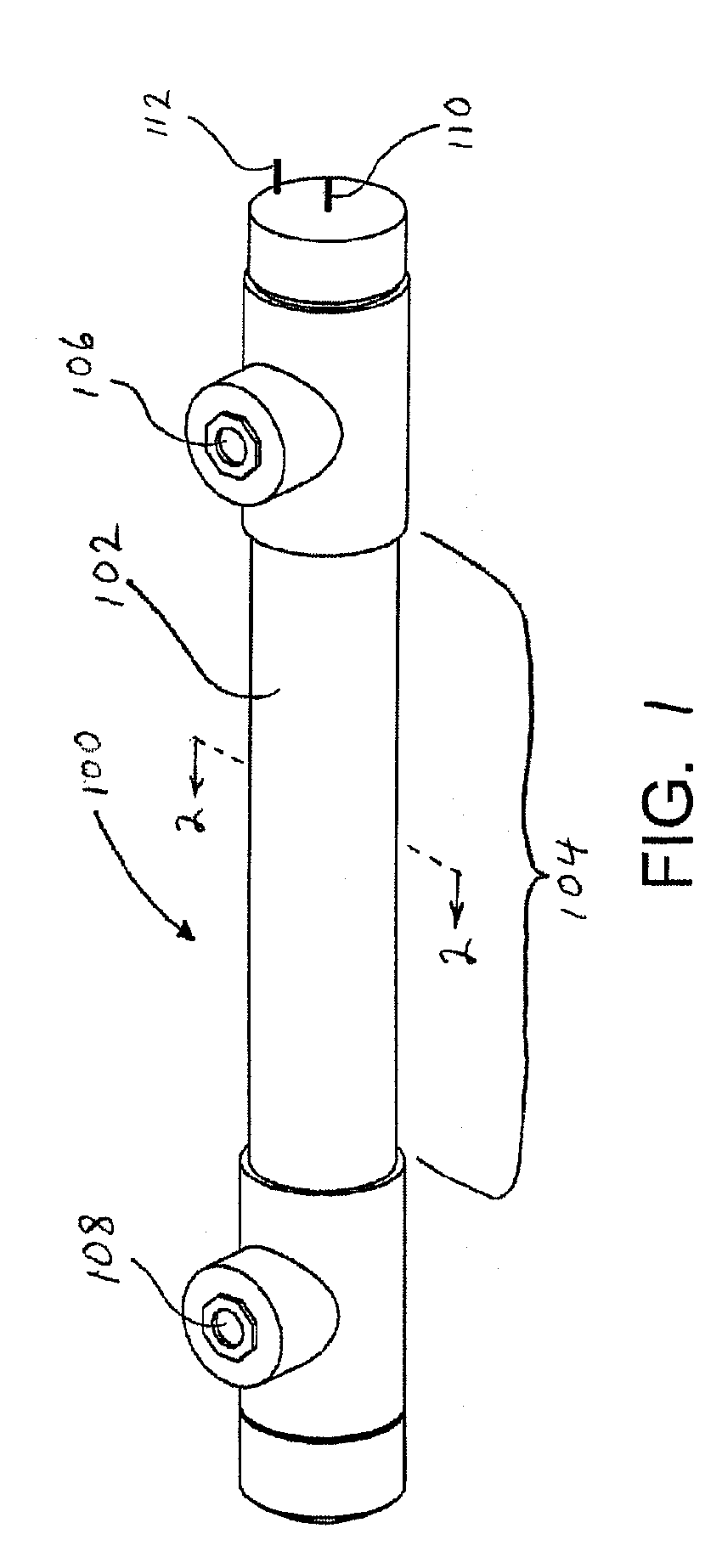
[0018]Reference is now made to the accompanying drawings, to assist in illustrating the various aspects and features of the present invention. In this regard, the following descriptions of particular embodiments for an electrocoagulation reactor, the spirally wound assembly thereof, and systems, methods and uses including an electrocoagulation reactor, are presented herein for purposes of illustration and description. Furthermore, the description is not intended to limit the invention to the particular form or forms disclosed herein. Consequently, variations and modifications commensurate with the teachings presented herein, and the skill and knowledge of the relevant art, are within the scope of the present invention. The embodiments described herein are further intended to explain the best modes known of practicing the invention and to enable others skilled in the art to utilize the invention in such, or other embodiments and with various modifications required by the particular a...


PUM

PropertyMeasurementUnit
separation distanceaaaaaaaaaa
internal diameteraaaaaaaaaa
lengthaaaaaaaaaa

Abstract

An electrocoagulation reactor, and water purification systems and methods using the reactor, are provided. The electrocoagulation reactor has a spirally wound assembly in which electrocoagulation treatment takes place. The spirally wound assembly includes electrode sheets spirally wound in spaced relation with an area for fluid flow in the space between the electrode sheets.

Description

CROSS-REFERENCE TO RELATED APPLICATIONS[0001]This application claims priority to U.S. Provisional Patent Application 60 / 948293 filed Jul. 6, 2007, the entire contents of each and every portion of which is incorporated herein by reference as if set forth herein in full. This application is a continuation of prior international patent application PCT / US08 / 69285, which designated the United States, filed Jul. 6, 2008, the entire contents of each and every portion of which is incorporated herein by reference as is set forth herein in full.FIELD OF THE INVENTION[0002]The present invention relates to electrocoagulation treatment of aqueous liquids.BACKGROUND OF THE INVENTION[0003]Electrocoagulation is a water treatment technique in which an aqueous liquid to be treated is passed between two electrically powered electrodes, an anode and a cathode, connected to an electrical power source that causes an electrical potential to be applied between the electrodes and electrical current to flow ...

Claims


Application Information

Patent Timeline
Patent Type & Authority Applications(United States)
IPC IPC(8): C02F1/463
CPCC02F1/001C02F1/463C02F2201/4617C02F2201/003C02F2201/46125C02F2001/46152
Inventor HEISS, CHRISTOPHER WILLIAM
Owner POWELL WATER SYST
Why Eureka
Try Eureka