
Continuous electrolyzed oxidizing/reduction water generator device

a generator device and electrolyzed technology, applied in the field of water treatment technology, can solve the problems of limited electrolytic bath capacity and electrode area, quick deterioration of electrodes, and conventional electrolyzed oxidizing/reduction water generator devices, etc., to increase the water electrolyzing capacity, improve water disinfection capabilities, and extend the surface area of electrodes.

Inactive Publication Date: 2015-04-14
HUNG YUN CHI
View PDF11 Cites 2 Cited by
  • Summary
  • Abstract
  • Description
  • Claims
  • Application Information

AI Technical Summary

Benefits of technology

The technical solution described in this patent is a new design for an electrolyzed oxidizing / reducing water generator device. The design involves arranging both positive and negative electrodes in a parallel manner inside an acidic and alkali resistance pipeline, which increases the electrical discharge area and allows for faster and more efficient water electrolysis. The use of bent tubes to connect multiple generator units in series increases the total discharging electrode surface area. Additionally, the invention allows for the addition of potassium chloride, sodium chloride, or hydrochloric acid to improve water disinfection capabilities. Overall, this design allows for faster, more efficient, and improved water disinfection capabilities.

Problems solved by technology

However, conventional electrolyzed oxidizing / reduction water generator devices commonly have the drawbacks of limited electrolytic bath capacity and electrode area, quick deterioration of electrodes, ease of scaling, cleaning difficulty and short service life.
Further, commercial electrolyzed oxidizing / reduction water generator devices do not any function for setting and displaying electrolyzed water reduction potential.
However, the water passage in the measuring instrument may be clogged or partially clogged by impurities or cumulated calcium easily during measurement, leading to a measurement error.
Thus, a consumer cannot know accurately whether or not the electrolyzed reduction / oxidizing water meets the standards.
Further, most consumers doubt the effectiveness of electrolyzed reduction / oxidizing water in human body.

Method used


Image

  • Continuous electrolyzed oxidizing/reduction water generator device
  • Continuous electrolyzed oxidizing/reduction water generator device
  • Continuous electrolyzed oxidizing/reduction water generator device

Examples


Embodiment Construction

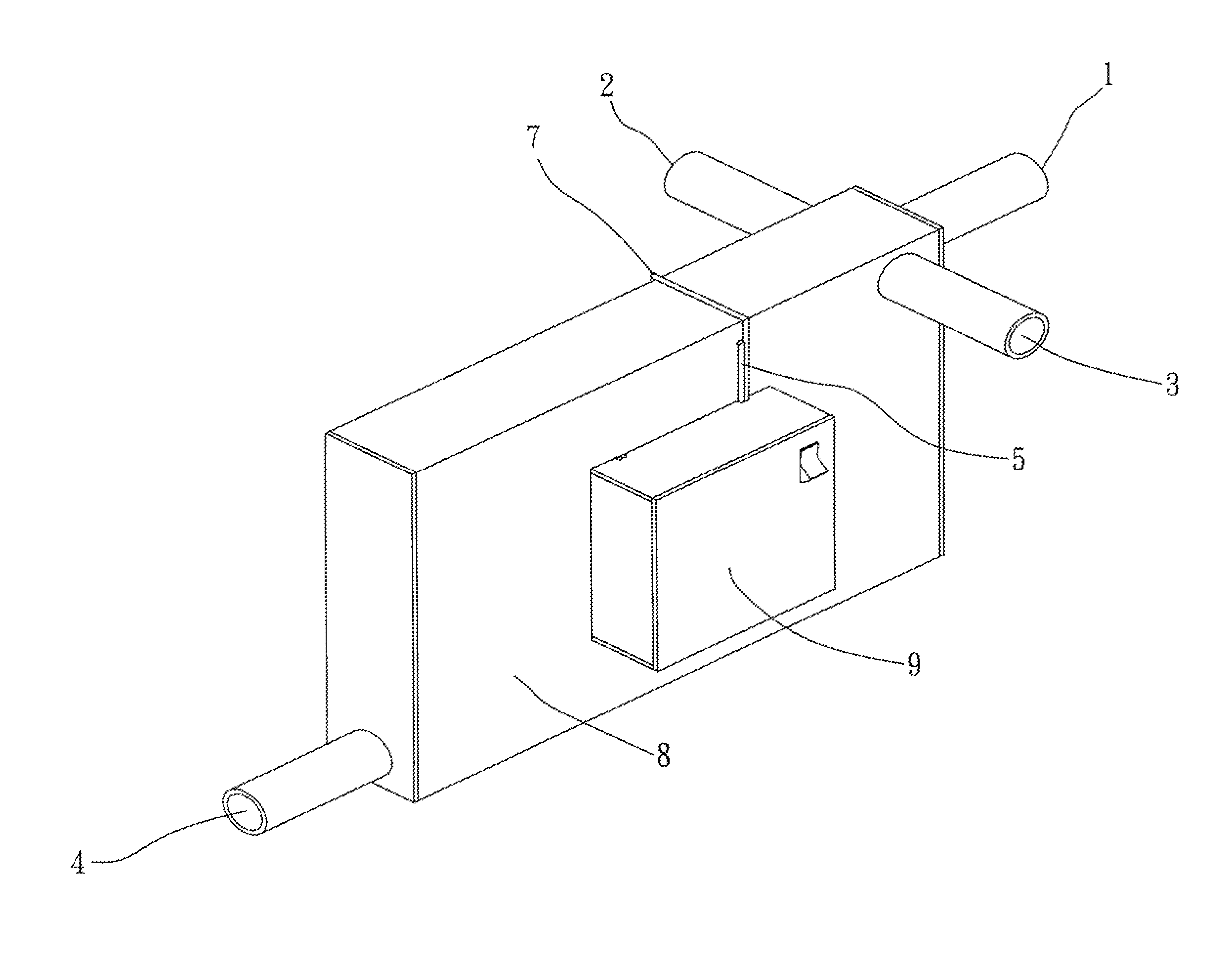
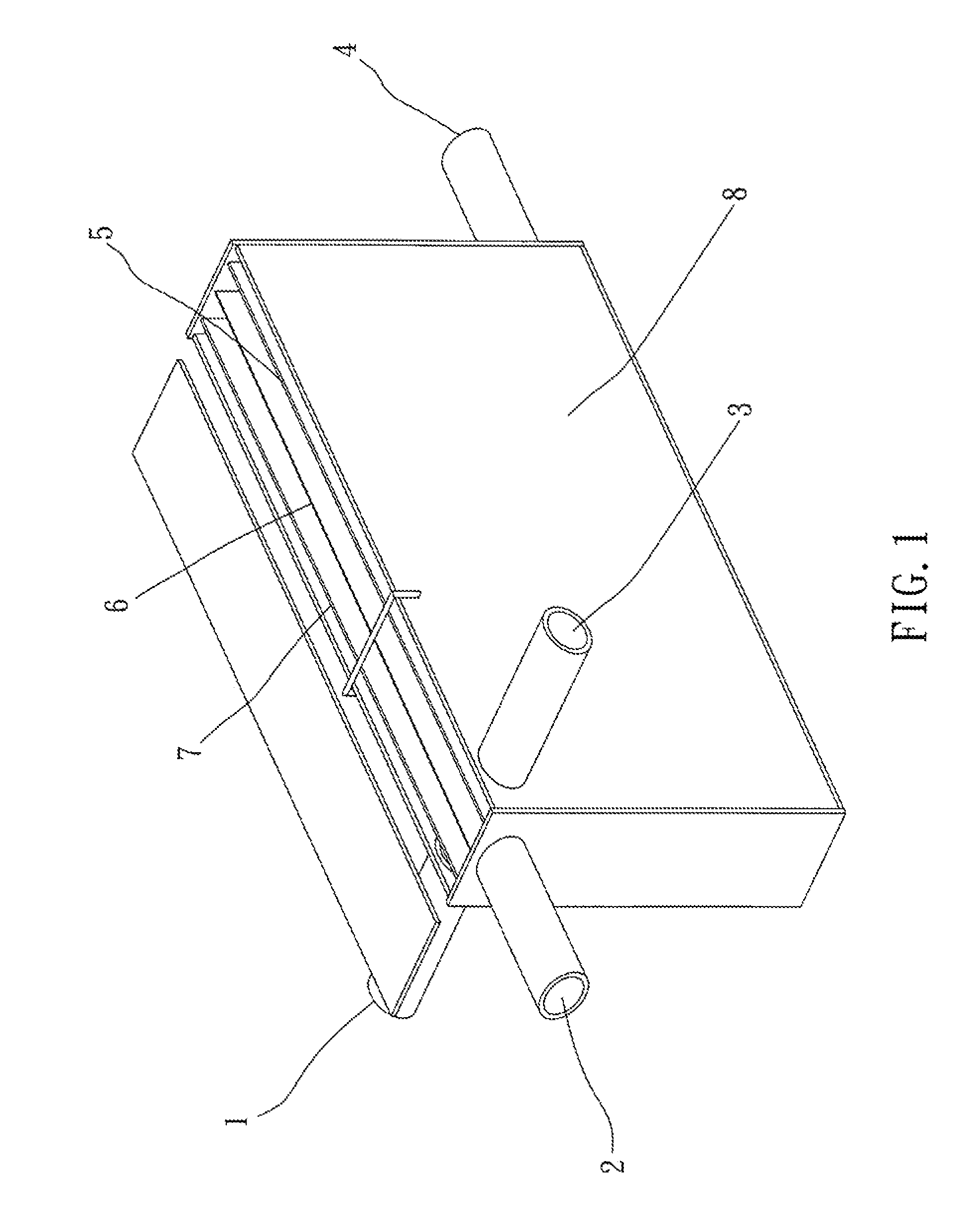
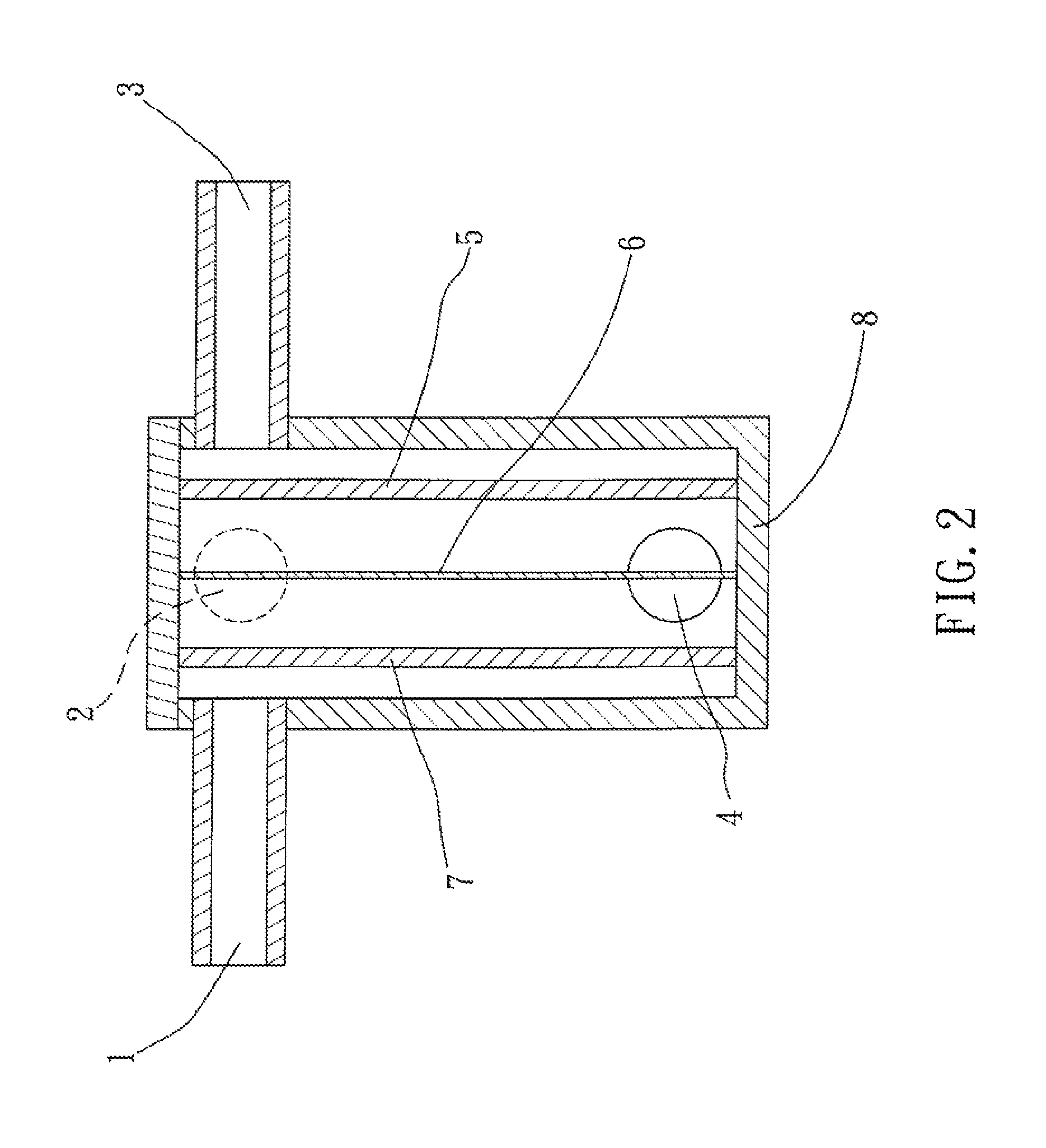
[0027]Referring to FIGS. 1, 2 and 3, a continuous electrolyzed oxidizing / reduction water generator device in accordance with a first embodiment of the present invention is shown. The continuous electrolyzed oxidizing / reduction water generator device comprises a positive electrode 7, a negative electrode 5, a cation exchange membrane 6 an electrically insulative housing 8, and an electric control box 9.

[0028]The electrically insulative housing 8 is a box member having a rectangular cross section and made of acid, alkali and pressure resistant engineering plastics, defining a water inlet 4 at one side and three water outlets 1;2;3 at an opposite side. The top panel of the electrically insulative housing 8 is detachable, however, it must be strictly sealed during application. The positive electrode 7 and the negative electrode 5 are longitudinally mounted inside the electrically insulative housing 8 in a parallel manner and equally spaced between the two opposite sidewalk of the electr...


PUM

PropertyMeasurementUnit
distanceaaaaaaaaaa
distanceaaaaaaaaaa
voltageaaaaaaaaaa

Abstract

A continuous electrolyzed oxidizing / reduction water generator device includes an electrically insulative housing which is an acid, alkali and pressure resistant box with a water inlet and multiple water outlets on opposing sides, positive and negative electrodes are mounted in the electrically insulative housing in parallel and equally spaced by a cation exchange membrane, and an electric control box to provide high voltage DC across the positive and negative electrodes to oxidize intake water into electrolyzed oxidizing / reduction water. Multiple generator units may be connected in series.

Description

BACKGROUND OF THE INVENTION[0001]1. Field of the Invention[0002]The present invention relates to water treatment technology and more particularly, a continuous electrolyzed oxidizing / reduction water generator device for efficiently electrolyzing water into electrolyzed oxidizing / reduction water.[0003]2. Description of the Related Art[0004]Electrolyzed water or electrolyzed oxidizing water is produced by the electrolysis of ordinary city water containing dissolved sodium chloride. The electrolysis occurs in a specially designed reactor which allows the separation of the cathodic and anodic solutions. In this process, electrolytic reduction water is produced at the cathode side, and electrolytic oxidizing water is produced at the anode side. During electrolysis, a cation exchange membrane is provided between the positive electrode and the negative electrode, allowing ions to pass therethrough and to form an electric current, and prohibiting neutralization of electrolyzed molecules bet...

Claims


Application Information

Patent Timeline
Patent Type & Authority Patents(United States)
IPC IPC(8): C02F1/461C25B9/08A61K35/02A61P13/12A61P35/00C02F1/46C25B9/19
CPCC02F1/46104C02F1/4618C02F2001/46142C02F2001/46195C02F2209/04C02F2303/02C02F2303/04A61P13/12A61P35/00A61P3/10C25B9/19C25B15/08
Inventor HUNG, YUN-CHI
Owner HUNG YUN CHI
Learn More