PHY clock synchronization in a BPL network

a phy clock and synchronization technology, applied in the field of synchronization between units in a communication network, can solve the problems of inability to fully synchronize the phy level clocks of neighboring units, inability to share a single clock source, and inability to optimize multi-hop environment, etc., to achieve greater phy clock synchronization, less data exchange, and low level modulation

Inactive Publication Date: 2011-01-18
MAIN NET COMM
View PDF16 Cites 5 Cited by
  • Summary
  • Abstract
  • Description
  • Claims
  • Application Information

AI Technical Summary

Benefits of technology

[0009]The present embodiments provide a method and apparatus for point to point synchronization in a network used for communication. Each unit of the network maintains course PHY clock synchronization information of neighboring units, the coarse synchronization allowing relatively low level modulation to be used in communication sessions between the units. When a higher level modulation session is needed then the course synchronization information is used as the basis for obtaining greater PHY clock synchronization. Increasing the synchronization from the coarse level requires less data exchange than obtaining high level synchronization from scratch, and thus allows use of components within the handshake protocols to transfer the necessary clock data.
[0013]using the exchanged clock information, increasing a level of synchronization above the coarse background synchronization level, thereby to support the required modulation level.
[0023]a second level synchronization unit configured to utilize session handshakes to increase a synchronization level with a neighboring communication unit beyond that supported by a respective coarse synchronization, thereby to allow a communication session to be held at a higher modulation level than the coarse level synchronization is able to support.
[0024]In an embodiment, the second level synchronization unit is configured to exchange at least partial clock information with the neighboring unit during the session handshake, thereby to increase the synchronization level.

Problems solved by technology

However, this concept was intended for and works best on single hops where all the units hear each other and the central clock more or less directly, and is not optimal for the multi hop environment which is generally the case in a BPL network or a BPL part of a complex of BPL and AV networks.
The power line network being used can be quite large and individual units can be connected to numerous neighboring units and those units to numerous others, rendering it impractical to share a single clock source.
The result is that PHY level clocks of the neighboring units unable to share a clock source may end up not being fully synchronized.
However as the number of units increases, the number of beacons increases exponentially, becoming harder to schedule.
The beacons are themselves liable to collision, leading to loss of the corresponding data.
However if each unit uses what is in effect a different clock source, the PHY clocks may be corrupted and consequently loose their synchronization.
Without good synchronization, the PHY clocks are not the same, and ppm (parts per million) differences create drifts over time.

Method used


Image

  • PHY clock synchronization in a BPL network
  • PHY clock synchronization in a BPL network
  • PHY clock synchronization in a BPL network

Examples


Embodiment Construction

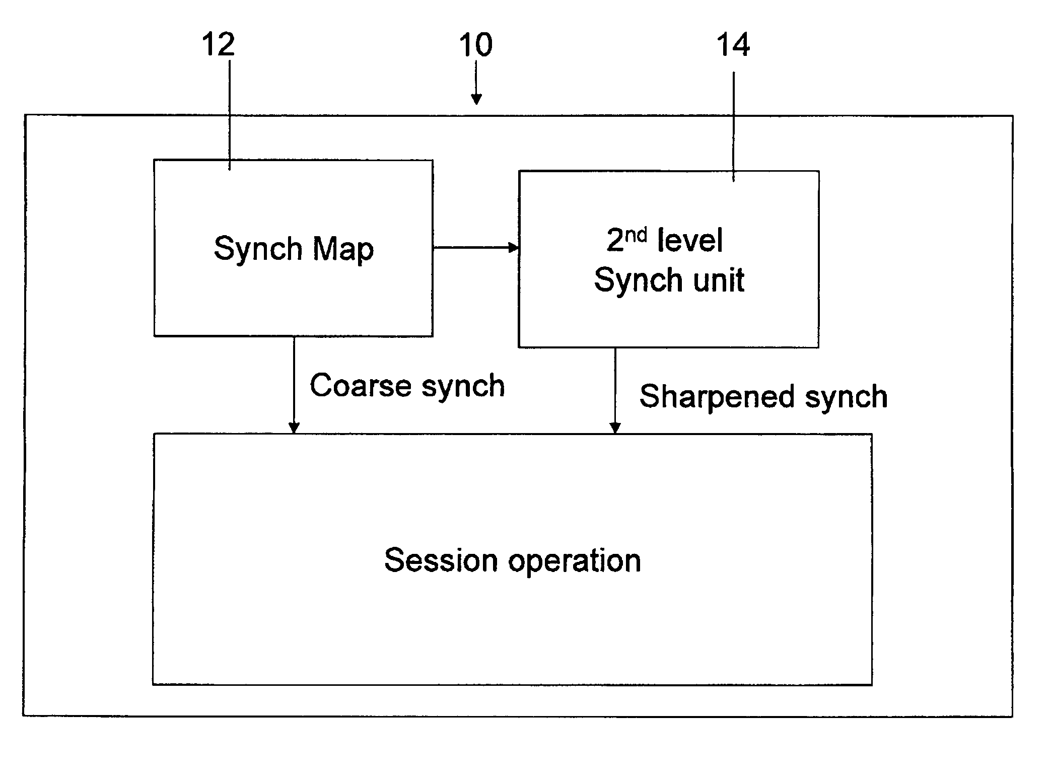
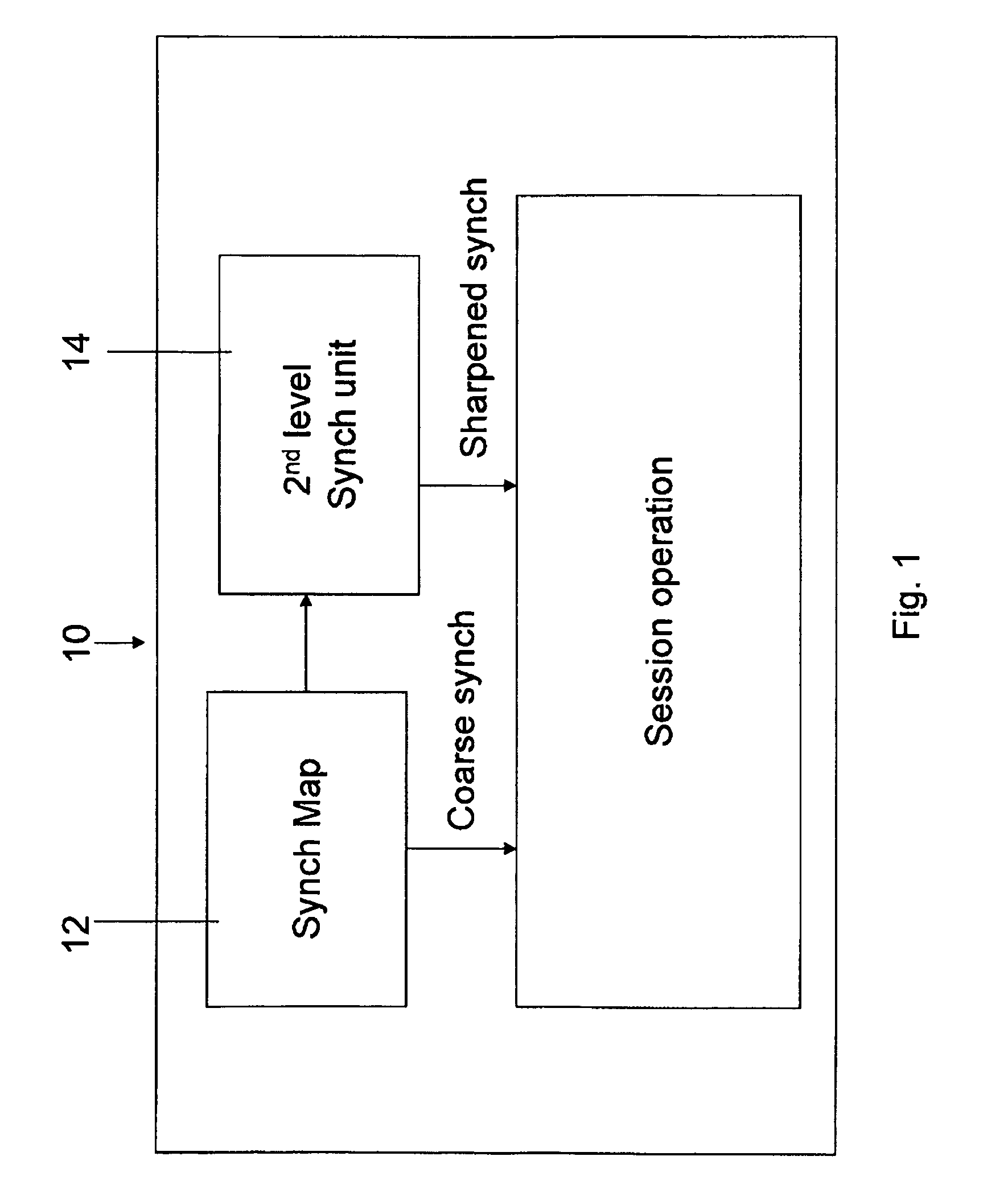
[0041]The present invention, in some embodiments thereof, relates to a method and apparatus for synchronization of communication units in a power line communication network. In a BPL network, communication is in sessions between pairs of units distributed over the power lines. The sessions require a certain level of synchronization between the communicating units depending on the level of modulation required for the particular communication. Higher levels of modulation require higher levels of synchronization. Higher levels of synchronization are otherwise referred to herein as sharper synchronization.

[0042]The power line is generally a noisy environment and the higher levels of modulation may not always be available due to the current noise level. Nevertheless it is desirable to utilize the higher modulations wherever possible. Thus it is common that different sessions select the highest modulation level available in view of the session needs.

[0043]As discussed in the background, h...


PUM


Abstract

A method and a communication modem for broadband communication over power transmission lines. The modem includes a coarse level synchronization mapping unit which maintains a regularly updated coarse level clock synchronization map of neighboring communication units with which it is likely to exchange communications; and a second level synchronization unit which utilizes session handshakes and session data capacity to increase the synchronization level with a neighboring communication unit to allow a communication session to be held at a higher modulation level than the coarse level synchronization is able to support.

Description

RELATED APPLICATIONS[0001]This application is a National Phase Application of PCT Patent Application No. PCT / IL2007 / 001379 having International Filing Date of Nov. 8, 2007, which claims benefit under 35 U.S.C. §119(e) from U.S. Provisional Patent Application No. 60 / 865,453, filed Nov. 13, 2006, and U.S. Provisional Patent Application No. 60 / 864,987, filed Nov. 9, 2006. The contents of the above Application are all incorporated herein by reference.FIELD AND BACKGROUND OF THE INVENTION[0002]The present invention, in some embodiments thereof, relates to synchronization between units in a communication network, and more particularly, but not exclusively, to the issue of synchronization in a broadband over power line (BPL) network.[0003]Power line communications networks typically require modems or communication nodes or communication units that are connected to the electric grid, to provide a network topology based on the electric grid connecting these nodes. Any two nodes in a power li...

Claims


Application Information

Patent Timeline
Patent Type & Authority Patents(United States)
IPC IPC(8): H04L7/00
CPCH04B3/54H04J3/0638H04B2203/5425
Inventor GOLDFISHER, SHMUELGEVA, EREZ
Owner MAIN NET COMM
Why Eureka
Try Eureka