Method of performing a finite element analysis of a composite structure

Inactive Publication Date: 2011-01-25
SAEBI NASSER
View PDF10 Cites 13 Cited by
  • Summary
  • Abstract
  • Description
  • Claims
  • Application Information

AI Technical Summary

Benefits of technology

The surface coating material of the composite building is constructed. This is accomplished by copying the surface mesh lines of the core and by using the surface mesh to construct plate or shell elements on top of the surface mesh of the core. The copying is done at zero distance from the surface mesh

Problems solved by technology

However, a composite structure is made of at least two different materials and, therefore, is not homogenous.
Composite structures are very complex to analyze.
Therefore, these programs could not provide a valid solution for a complex composite structure.

Method used


Image

  • Method of performing a finite element analysis of a composite structure
  • Method of performing a finite element analysis of a composite structure
  • Method of performing a finite element analysis of a composite structure

Examples


Embodiment Construction

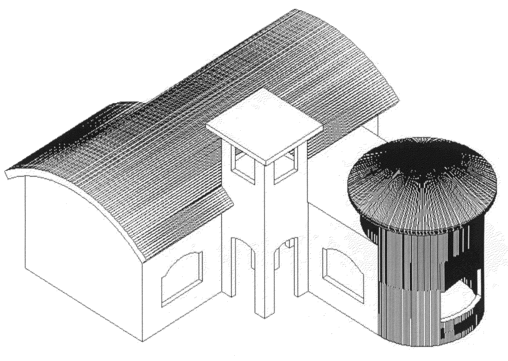
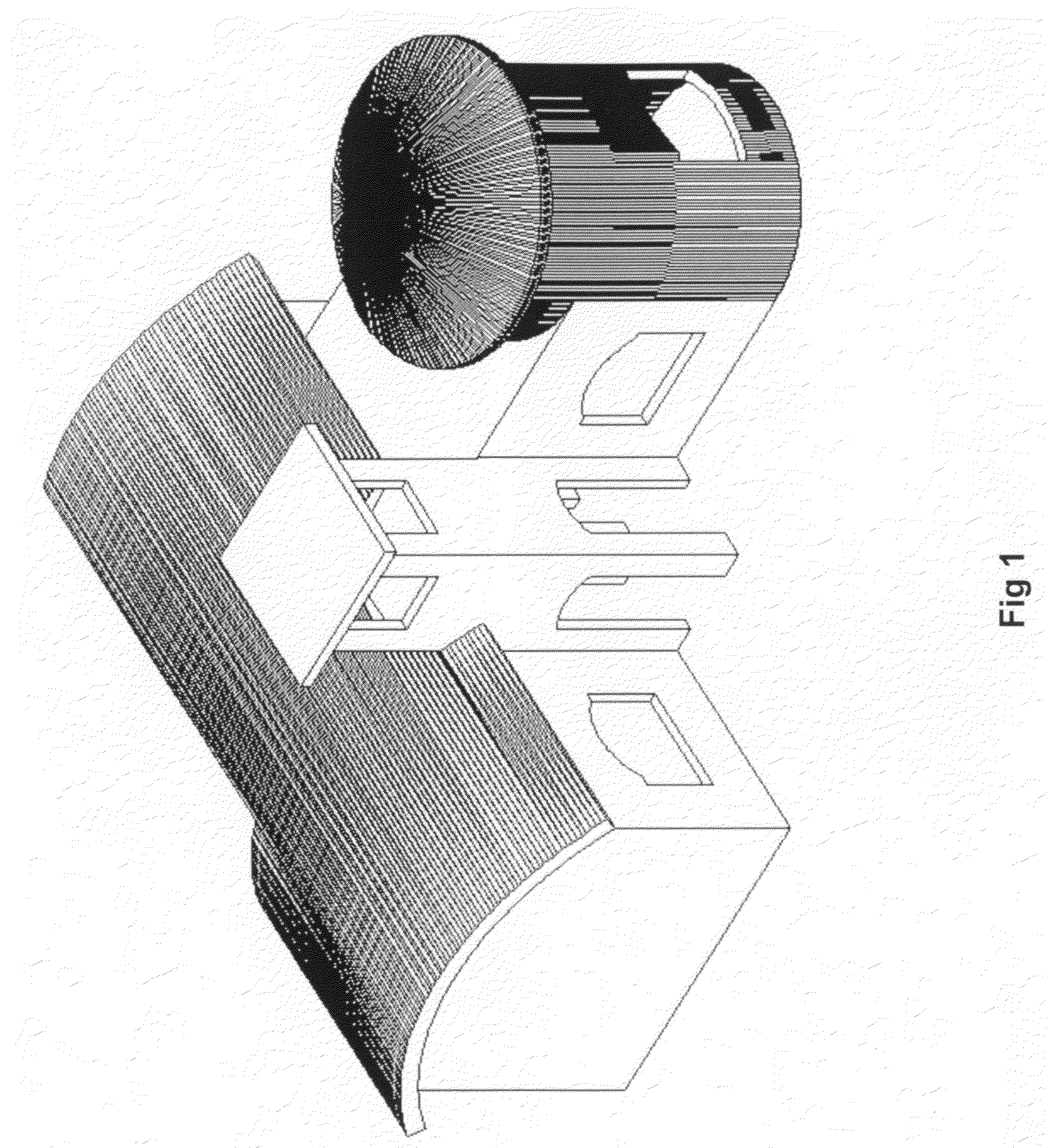
FIG. 1 shows the rendering of a building created in 3D solid format using an CAD program or software. The program used here is Mechanical Desktop. The CAD program may also be a program or software, such as AutoCAD, Solidworks, Alibre, etc.

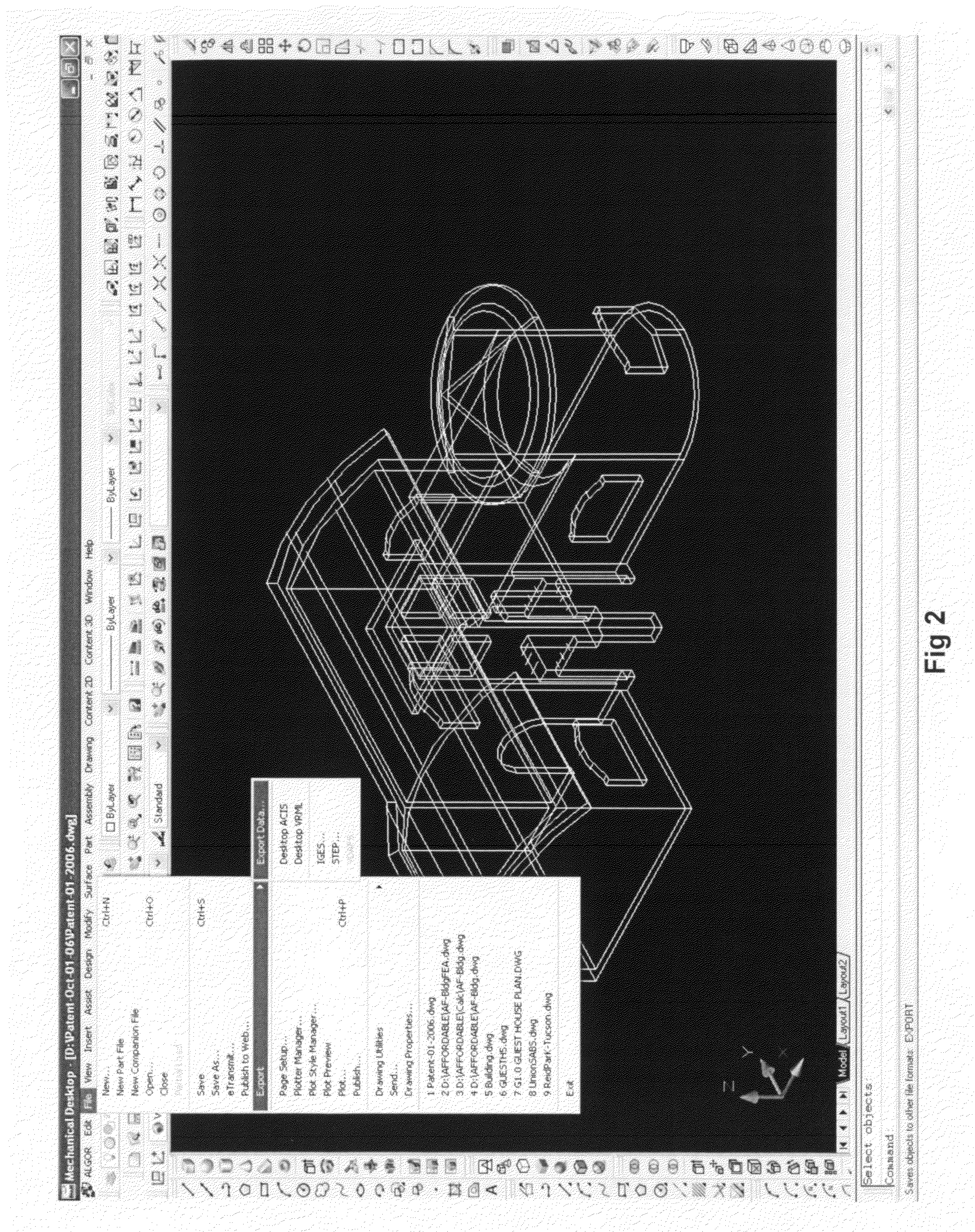
FIG. 2 shows the exporting of the 3D CAD drawing file using a compatible format that can be exported out of the CAD program (Mechanical Desktop) and imported by a Finite Element Analysis (FEA) program or software, such as Algor FEMPRO (FIG. 4). Depending on the FEA program, a different output or export format defining the solid model is selected. These formats maybe of the file type that have the extension STEP, IGES and SAT. The building is to be worked on in one piece or united. In this example, the name of the CAD file being exported in SAT format is named “Patent-01-2006.dwg” which after the conversion it is named “Patent-01-2006.sat”. This figure shows the exporting of the CAD file into a sat file. The exporting is accomplished by clicking on ...


PUM


Abstract

The invention provides a method of analyzing a building made from a core of foam plastic which is coated on the inside and outside with a strengthening coating. The building is designed in a CAD program. Then, the building surfaces are meshed in an automeshing program as one piece. Plates are added to the inner, outer and edge surfaces of the core by using copying at zero distance. The core is Solid Meshed. The boundary conditions are chosen for the boundary nodes. Appropriate characteristics of the EPS and GFRC have been assigned to the core and plates. A FEA analysis can be run.

Description

This application is related to U.S. Pat. No. 6,721,684, granted to the inventor, in which the core of the composite building was created by using the manual method of dividing the solid core geometry of the CAD model into bricks and tetrahedral elements (FIGS. 67 through 87 of that patent).This application is also related to the nonprovisional patent application claiming priority from provisional patent application Ser. No. 60 / 848,554, filed Sep. 20, 2006 which is incorporated by reference.BACKGROUND OF THE INVENTIONThis invention discloses an improvement on U.S. Pat. No. 6,721,684 which disclosed a method of performing the Finite Element Analysis (FEA) of a composite structure using a FEA program, such as Algor FEMPRO. Now, in these programs, the solid, shell, or plate structure can be divided into discrete meshes by a powerful automeshing portion of the program. The program has three choices of meshing—Solid meshing (meshing of the Solid or core), Midplane meshing (meshing at the ...

Claims


Application Information

Patent Timeline
IPC IPC(8): G06F17/50
CPCG06F17/5004G06F17/5018G06F30/13G06F30/23
Inventor SAEBI, NASSER
Owner SAEBI NASSER
Why Eureka
Try Eureka