Tower foundation, in particular for a wind energy turbine

a technology of towers and towers, applied in the field of hybrid towers, can solve the problems of increasing the height of the towers, difficult to seal the gap, and increasing the diameter of the rotor of wind energy turbines

Inactive Publication Date: 2011-02-01
GENERAL ELECTRIC CO
View PDF16 Cites 14 Cited by
  • Summary
  • Abstract
  • Description
  • Claims
  • Application Information

AI Technical Summary

Benefits of technology

[0018]Due to the distribution of the shear forces from the steel tower segment to the concrete tower segment, significant and, accordingly, undesired tension force concentrations can be prevented. Therefore, a hybrid tower can be obtained without a gap between adjacent steel and concrete tower segments and without the danger of the formation of cracks in the concrete wall of the concrete tower segment.
[0022]The kind of connection between a tubular concrete tower segment and a tubular steel segment according to the present invention can be used for reinforced concrete tower segments which may include pre-stressing elements extending axially through at least the embedment portion of the concrete tower segment. In a tower segment made of reinforced concrete (without pre-stressing elements) the anchoring elements of the steel tower segment can protrude from either the inner or the outer surface or from both surfaces. If a concrete tower segment including pre-stressed concrete having pre-stressing elements is used, the anchoring elements should project from that side of the steel tower segment facing the pre-stressing elements. Due to this arrangement, the anchoring elements interact with the pre-stressed portion of the concrete tower segment which with regard to the distributed introduction of shear forces is advantageous.

Problems solved by technology

Further, increasing rotor diameter size of wind energy turbines requires increasing heights of the towers.
It is difficult to seal the gap 4 because the dimensions of the gap are likely to fluctuate, particularly when the tower is subjected to radial loads.

Method used


Image

  • Tower foundation, in particular for a wind energy turbine
  • Tower foundation, in particular for a wind energy turbine
  • Tower foundation, in particular for a wind energy turbine

Examples


Embodiment Construction

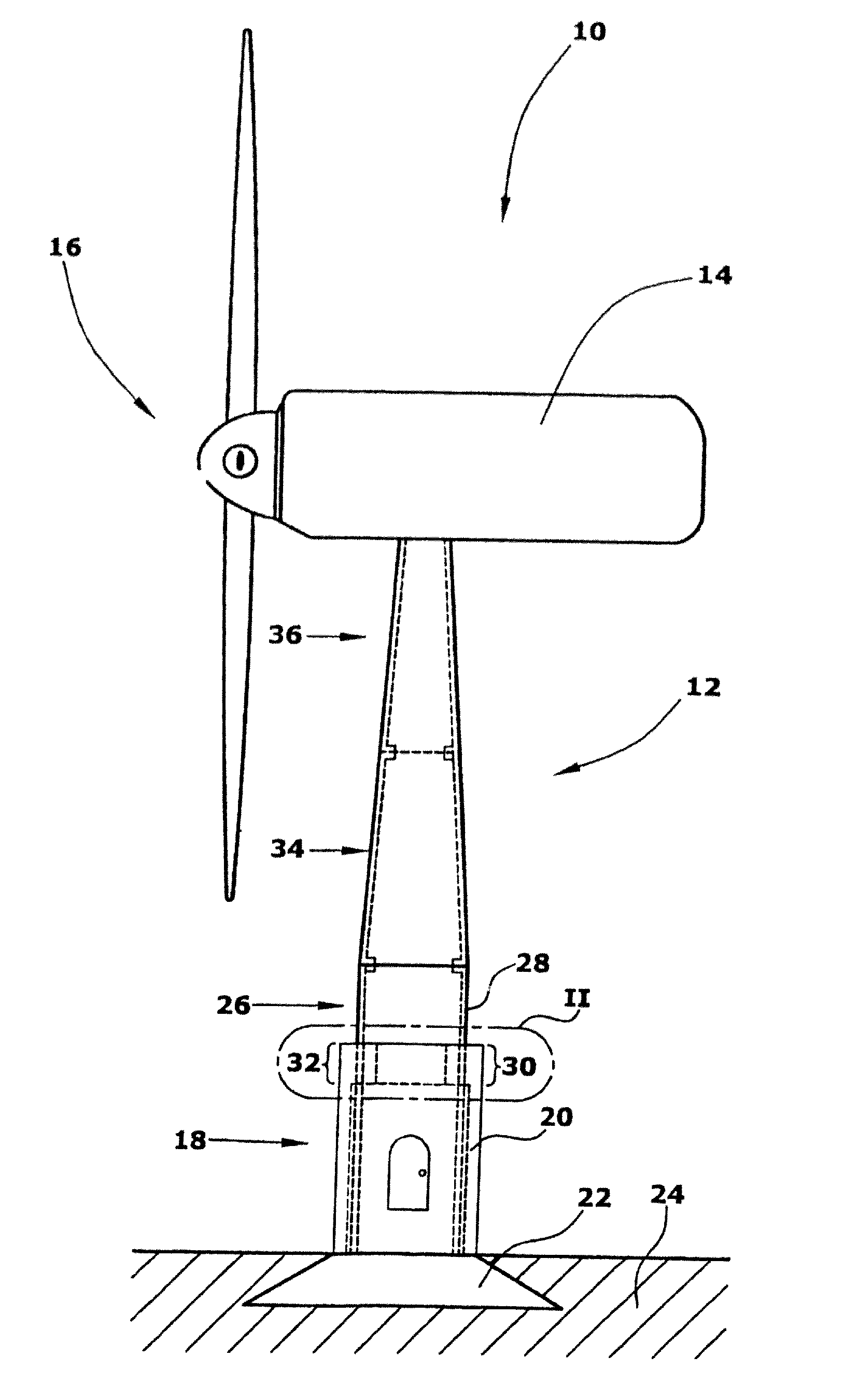
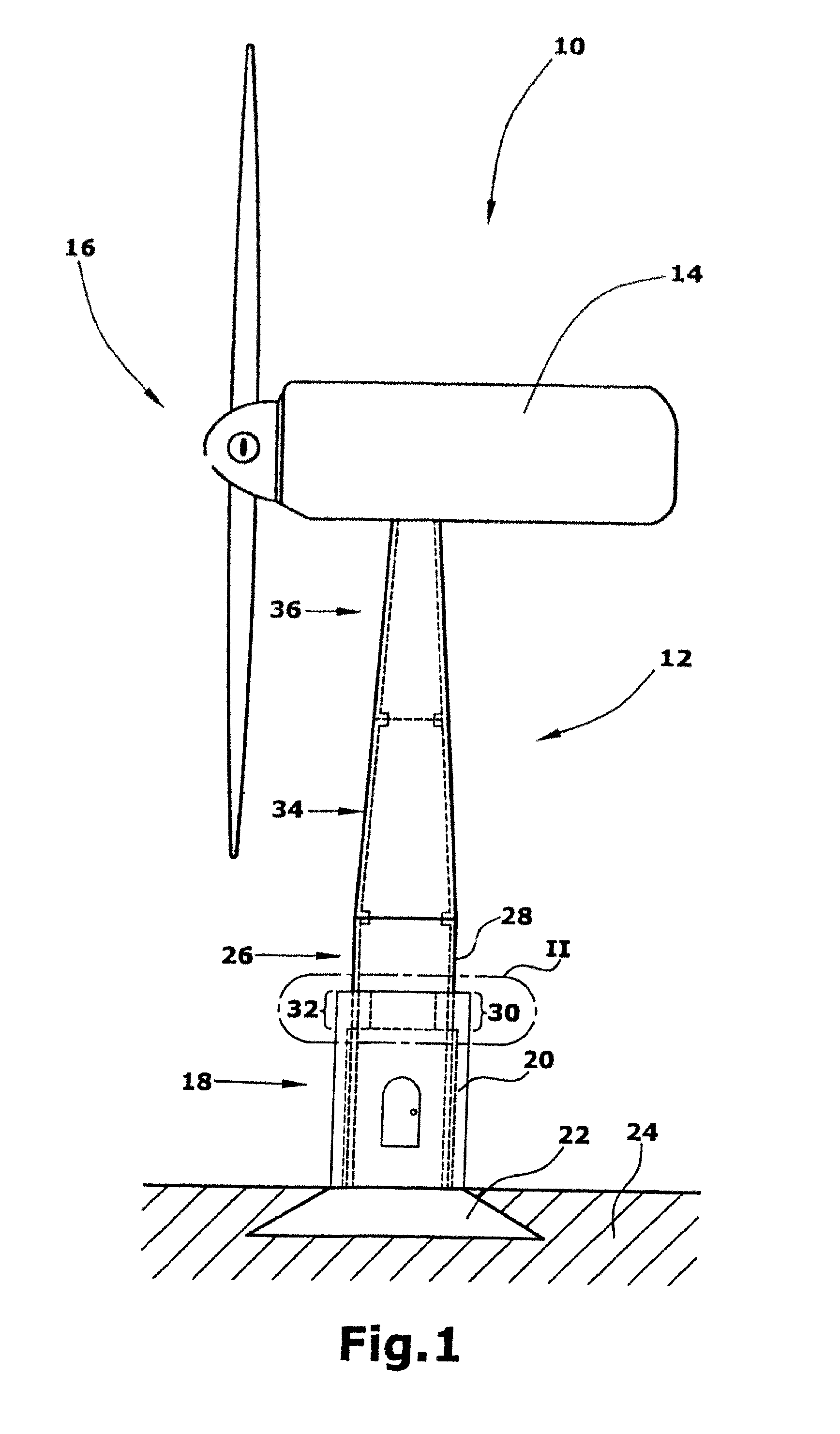
[0030]FIG. 1 shows a side view of a wind energy turbine 10. The wind energy turbine 10 includes a tower 12 and a nacelle 14 rotatably arranged on top of the tower 12. The nacelle 14 is provided with a rotor 16 mounted rotatably around a horizontal axis. The nacelle 14 is mounted at the tower 12 while being rotatable around a vertical axis. Although in FIG. 1 a wind energy turbine 10 having a rotor being rotatable around a horizontal axis is shown, the present invention is not limited to such wind energy turbine designs but can also be used in connection with a wind energy turbine having a rotor being rotatable around a vertical axis.

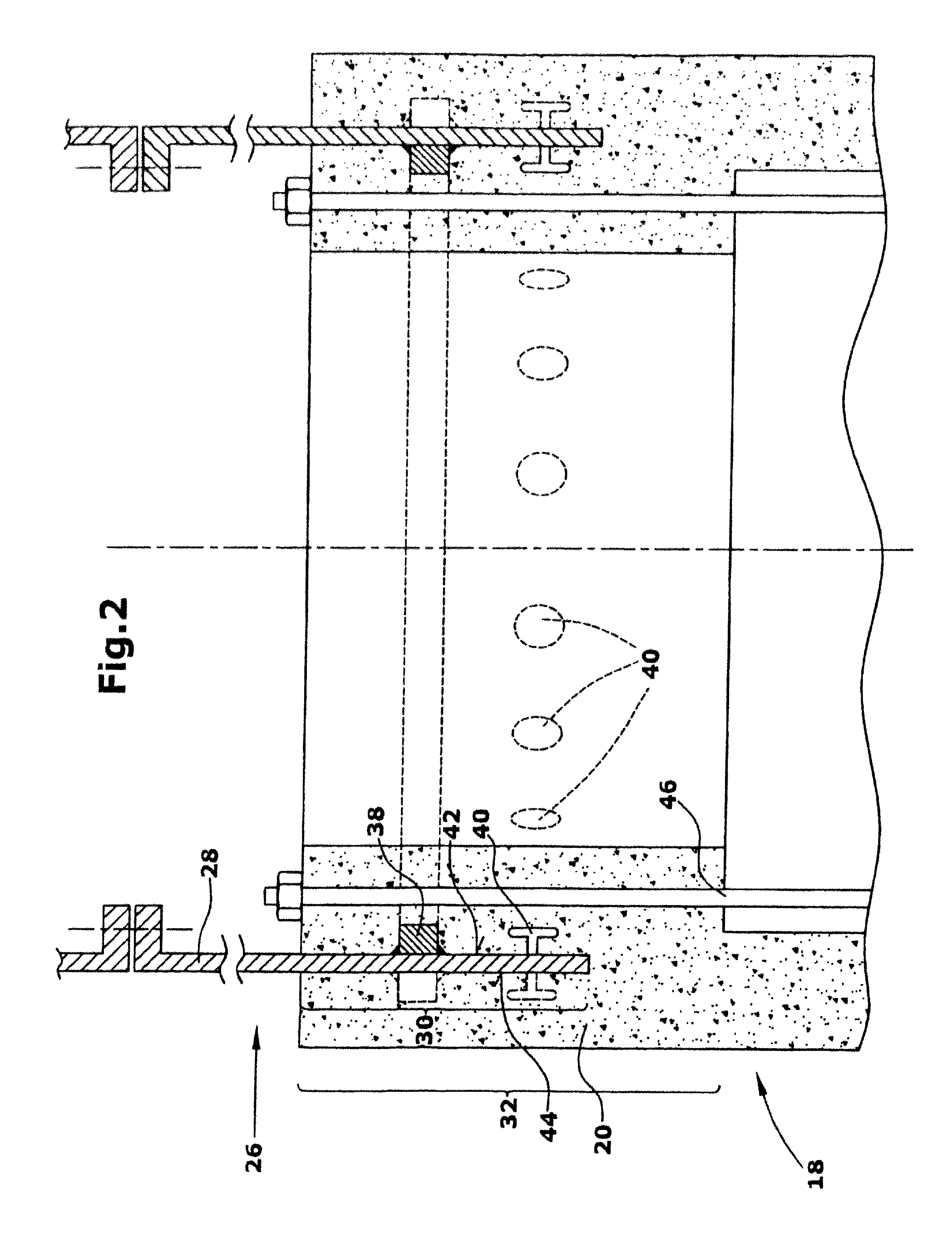
[0031]As can be seen from FIG. 1, the tower 12 includes several tubular tower segments. Specifically in this embodiment, a first tower segment 18 including a wall 20 of concrete is arranged at the base portion of the tower 12. As shown herein, the first tower segment is tubular in shape. Moreover, the first tower segment 18 is provided with a foundation ...


PUM


Abstract

A tower, in particular for a wind energy turbine, comprises a first tower segment (18) having a wall (20) comprising concrete material and a second tower segment (26) having a wall (28) comprising steel. The wall (28) of the second tower segment (26) comprises an end portion (30) embedded in an embedent portion (32) of the wall (20) of the first tower segment (18). The second tower segment (26) within its embedded end portion (30) comprises at least one anchoring element (38, 40, 52) projecting radially from an inner or an outer surface (42, 44) or both inner and outer surfaces (42, 44) of the wall (28) of the second tower segment (26), the anchoring elements (38, 40, 52) being arranged along an axial direction of the second tower segment (26).

Description

CROSS-REFERENCE TO RELATED APPLICATION[0001]This application is a National Phase Application of, and claims priority to, International Application No. PCT / EP2003 / 008871, filed 9 Aug. 2003, entitled TOWER FOUNDATION, IN PARTICULAR FOR A WIND ENERGY TURBINE.BACKGROUND OF THE INVENTION[0002]1. Field of the Invention[0003]The present invention relates to a tower suitable in particular for a wind energy turbine. More specifically, the present invention relates to a hybrid tower including a tower segment comprising concrete material and at least one other tower segment comprising steel. In particular, the present invention is related to the connection between the concrete tower segment and the steel tower segment.[0004]2. Related Prior Art[0005]Towers for supporting diverse elements are well known and used in different technical fields. For example, tubular towers are used to support the nacelle of a wind energy turbine wherein the nacelle is rotatably mounted on top of the tower.[0006]In...

Claims


Application Information

Patent Timeline
Patent Type & Authority Patents(United States)
IPC IPC(8): E02D27/32E02D27/42F03D1/00F03D11/04
CPCE02D27/42F03D11/045F05B2230/60F05B2240/912Y02E10/728F03D13/22Y02P70/50Y02E10/72
Inventor SEIDEL, MARC
Owner GENERAL ELECTRIC CO
Why Eureka
Try Eureka