Rotary cutting unit for trimming sheet material

a cutting unit and cutting board technology, applied in shearing machines, metal working devices, shearing apparatuses, etc., can solve the problems of prone to malfunction, affecting the clamping effect of sheet materials, and relatively complex construction, and achieve the effect of simple design

Inactive Publication Date: 2011-02-01
MONOLITH
View PDF33 Cites 28 Cited by
  • Summary
  • Abstract
  • Description
  • Claims
  • Application Information

AI Technical Summary

Benefits of technology

[0013]It is thus the object of the present invention to configure a rotary cutting unit so that with it, clamping of the sheet material is possible before the beginning of the cutting operation; it is of simple design and therefore inexpensive; and it is also suitable for trimming relatively thick sheet material or a relatively thick sheet material stack.
[0022]With this embodiment, the motion of the guide bar out of the initial position into the clamping position is therefore produced by the fact that actuation devices are actuated manually at both ends; this can occur successively or simultaneously. This embodiment has the advantage that a particularly uniform contact of the guide bar on the sheet material can be effected.

Problems solved by technology

A disadvantage of the rotary cutting units described above is that clamping of the sheet material is dependent on the action on the knife carriage, i.e. clamping is not accomplished until the cutting operation begins, and moreover is locally concentrated on the position of the knife carriage.
The above-described rotary cutting units secure the sheet material in position independently of the cutting operation, but are of relatively complex construction and therefore expensive and prone to malfunction.

Method used


Image

  • Rotary cutting unit for trimming sheet material
  • Rotary cutting unit for trimming sheet material
  • Rotary cutting unit for trimming sheet material

Examples


Embodiment Construction

)

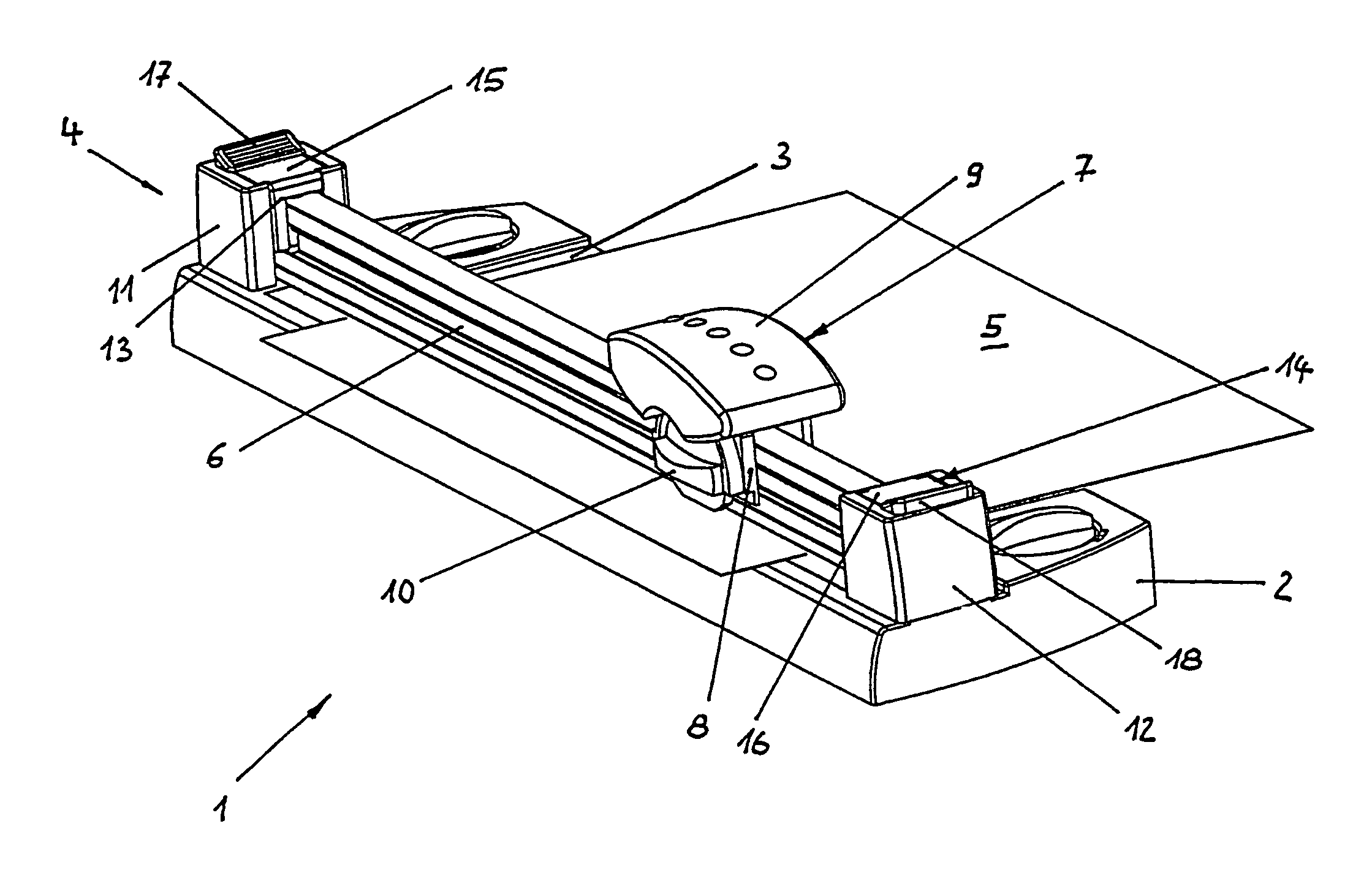
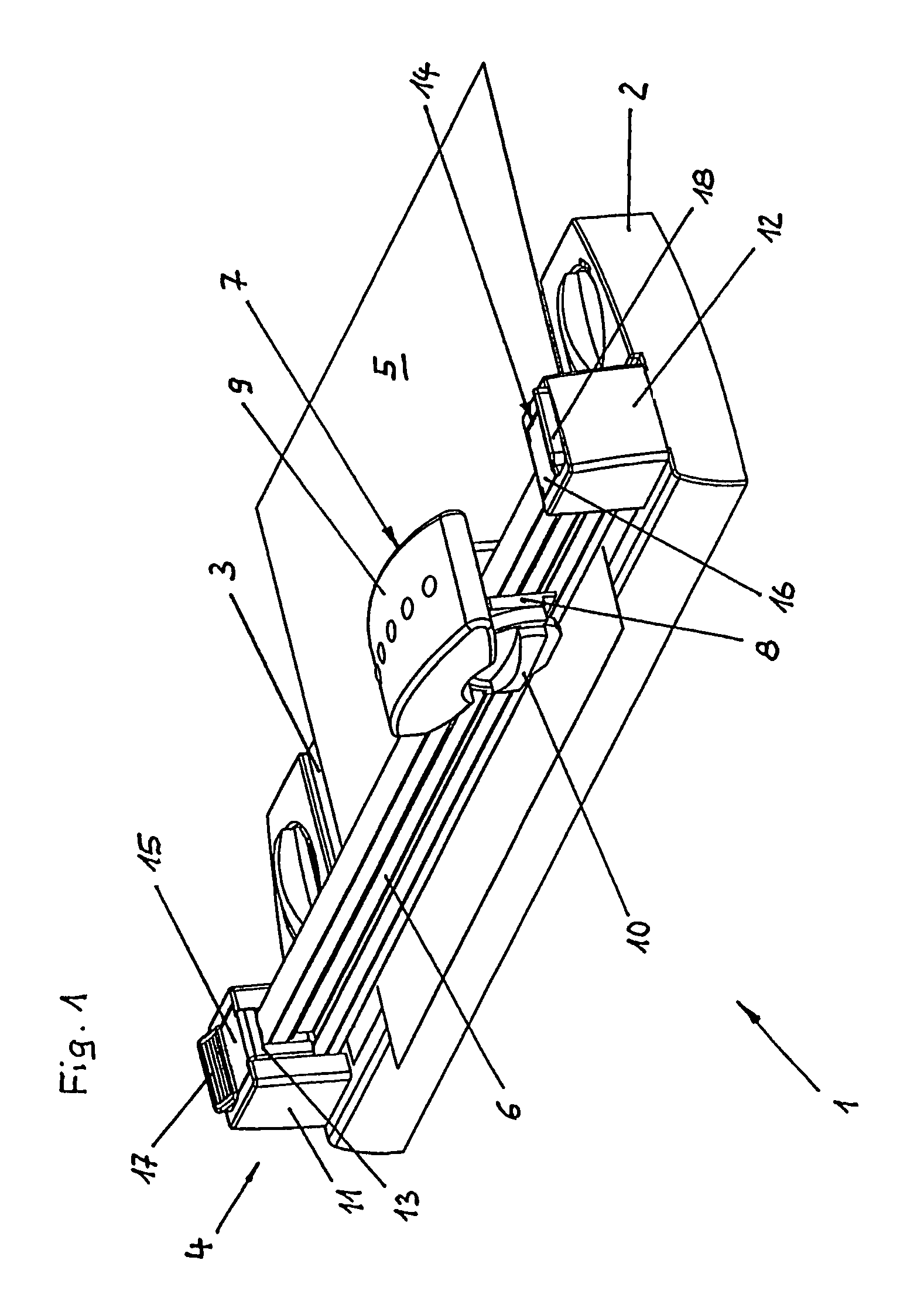
[0035]Rotary cutting unit 1 depicted in FIG. 1 comprises a support plate 2 that has on the upper side a horizontal sheet support surface 3. Arranged in the region of a longitudinal side of support plate 2 is a rotary cutting device 4 that serves to trim sheet material 5 placed on sheet support surface 3.

[0036]Rotary cutting device 4 comprises a guide bar 6 extending parallel to the longitudinal side of support plate 2 and parallel to sheet support surface 3; wrapping around both sides of said bar from the top is a knife carriage 7 that is displaceable along guide bar 6.

[0037]Knife carriage 7 is divided into an internally located guidance part (which is therefore not visible here) that fits positively around guide bar 6, and an external knife part 8 that is movable out of the raised position shown, against the action of a spring that is not visible here, vertically downward into a cutting position. Knife carriage 7 has at the top, for handling thereof, a hand grip 9 that is intended...


PUM

PropertyMeasurementUnit
distancesaaaaaaaaaa
forceaaaaaaaaaa
pressureaaaaaaaaaa

Abstract

A rotary cutting unit for trimming sheet material has a support plate for receiving the sheet material. The rotary cutting device having a guide bar with a displaceably guided knife carriage. A rotary knife is rotatably mounted on the knife carriage. The guide bar is guided between an initial raised position and a lowered clamping position. The guide bar includes a clamping surface for contact against sheet material. The guide bar has a force impinged upon it by a spring device, in the direction toward the initial position. An actuation device moves the guide bar out of the initial position into the clamping position. The guide bar is clamped in vertically movable fashion between the spring device and a further spring device. The second spring device has a spring action directed oppositely to the first.

Description

FIELD OF THE INVENTION[0001]The present invention relates to a rotary cutting unit for trimming sheet material.BACKGROUND OF THE INVENTION[0002]Cutting units are used chiefly in the office sector to trim sheets of paper or film, either individually or as a stack of sheet material. A feature common to such cutting units is that they have a horizontal support plate for placement of the sheet material, and that a cutting device is provided on at least one side of the support plate. Rotary cutting devices are suitable for producing particularly smooth cut edges.[0003]A rotary cutting device comprises a guide bar that extends parallel to one side of the support plate and also parallel to the surface of the support plate. A knife carriage is guided on the guide bar, displaceably along the guide bar. The knife carriage comprises a rotary knife that is mounted, freely rotatably about an axis extending horizontally and transversely to the longitudinal axis of the guide bar, on the knife carr...

Claims


Application Information

Patent Timeline
Patent Type & Authority Patents(United States)
IPC IPC(8): B26D7/02B26D1/18
CPCB26D7/025B26D1/185B26D2007/0087Y10T83/7507Y10T83/7763Y10T83/8822
Inventor LOIBL, BERND
Owner MONOLITH
Why Eureka
Try Eureka