Halftone dot formation method and apparatus for reducing layer thickness of coloring material inside halftone dots, and image formation apparatus

a technology of halftone dots and coloring materials, which is applied in the field of binarization processing techniques, can solve the problems of difficult compatibility of high possibility of this problem, and excessive amount of toner for halftone reproduction, so as to achieve effective thinning of the coloring material of the halftone-dot portion, reduce the thickness of the coloring material inside the halftone dot, and achieve the effect of reducing the amount of toner needed for the maximum density

Inactive Publication Date: 2011-02-01
FUJIFILM BUSINESS INNOVATION CORP
View PDF17 Cites 3 Cited by
  • Summary
  • Abstract
  • Description
  • Claims
  • Application Information

AI Technical Summary

Benefits of technology

[0020]The invention provides mechanism, which can thins a coloring-material layer in a halftone-dot portion while suppressing errors in densities of the output image and preventing image quality from deteriorating when density of a halftone-dot image is reproduced in a pseudo manner by using halftone dots, regardless of a printing method such as an electrophotographic method using powder as a coloring material or an inkjet method using ink as a coloring material.
[0024]a binarization processing section that, when the intensity of the image signal exceeds a predetermined value and is in a predetermined range, while maintaining contour dots, which are output dots contribute to formation of a contour of the halftone dot, to be the output dot, makes a part of dots inside the contour dots to be the actual non-output dot, and an image recording section that forms the halftone-dot image including the actual non-output dot in the halftone dot, on a basis of the binarized data generated by the binarization processing section. For example, as a shape of an original halftone dot, which is a process target, there are a so-called dot-shaped halftone dot (so-called dot screen), that is, an output dot growing into a substantially circle shape in response to density, and a line-shaped halftone dot having a structure in which a halftone dot is continued in a line shape in a range where the input image signal has a density equal to or larger than a predetermined density (so-called line screen). The dot screen is easy in forming a halftone dot, but is easily affected by disturbance at the time of image formation and color moire. To the contrary, the line screen has an advantage that it is less affected by the disturbance at the time of the image formation and the color moire.
[0025]If the invention of this application is applied to the dot-shaped halftone dot, the dot-shaped halftone dot becomes a ring-shaped halftone dot. Also, in the case of applying the invention of this application to the line-shaped halftone dot, for example, non-output dots are made to be continued in a line shape in the line-shaped halftone dot in a predetermined density range. That is, two methods can be adopted representatively; one is the case where gap is grown in the line-shaped structure to form a double line structure and the other is the case where non-output dots are maintained to be isolated in the line-shaped halftone dot, that is, the non-output dots are not continued in a line shape in the line-shaped halftone dot. The latter is better in reproducibility of the line structure.
[0026]Also, a pure-electronic mechanism may be configured so that the part of dots inside the contour dots is made to be a real non-output dot on electronic data representing the halftone dot, that is that an image recording signal inside the halftone dot is thinned out. Alternatively, a mechanism may be configured to modulate recording energy of the non-output dot inside the contour dots of the halftone dot on a basis of the binarized data generated by the binarization processing section so as to reduce an amount of coloring material.
[0028]According to the above configuration, only when the intensity of the image signal exceeds the predetermined value and is in the predetermined range, while the contour dots, which are the output dots contribute to the formation of the contour of the halftone dot, are maintained to be the output dot, the part of dots inside the contour dots is made to be the actual non-output dot. Therefore, a layer thickness of the coloring material inside the halftone dot can be reduced without the contour shape of the halftone dot made of the toner or ink being deformed.
[0029]Thereby, without deterioration of the image quality, the coloring material of the halftone-dot portion can be thinned effectively. Also, since a ratio of an amount of the coloring material contributing to light absorption is increased, the consumption amount of the coloring material can be reduced. Also, since the generation of the halftone dot and the generation of the gap are synthesized, control required for generating the gap dots inside the halftone dot is easy.

Problems solved by technology

Since the height of the piled-up toner is in many cases determined by an amount of toner required for the maximum density of the image, it may be an excessive amount of toner for halftone reproduction.
In particular, since the size of a halftone dot is small in a highlight tone area (low density region), there are high possibilities that this problem occurs.
However, it is difficult that the amount of toner needed for the maximum density is compatible with the amount of toner appropriate for the halftone dot reproduction.
However, as described above, in the halftone-dot structure for the halftone reproduction, the toner layer may become excessively thick in many cases, and therefore, the toner which makes a low contribution to light absorption exists on the paper.
However, in the FM screen such as the mechanisms disclosed in the patent document 1, since the density of the image is reproduced with a minute density of dots, which are invisible (30 μm or less), some of the integrated (clustered) minute halftone dots may be thinned out and areas of colored pixels may be too small to reproduce dots stably.
Accordingly, there may occur a phenomenon that the crush of some of the halftone dots is different from the crush of other halftone dots, which may result in image noises.
However, when many pixels are thinned out outside the halftone dots, since the size reduction of the halftone dots is significant but an operation of thinning out the coloring material in the half tone dot portion is weakened, an effect of making the halftone dots uniformly thin can not be expected.
In particular, since the size of the halftone dots becomes small in highlight tone area (low density area), there are high possibilities that the above-mentioned problems occur

Method used


Image

  • Halftone dot formation method and apparatus for reducing layer thickness of coloring material inside halftone dots, and image formation apparatus
  • Halftone dot formation method and apparatus for reducing layer thickness of coloring material inside halftone dots, and image formation apparatus
  • Halftone dot formation method and apparatus for reducing layer thickness of coloring material inside halftone dots, and image formation apparatus

Examples


first embodiment

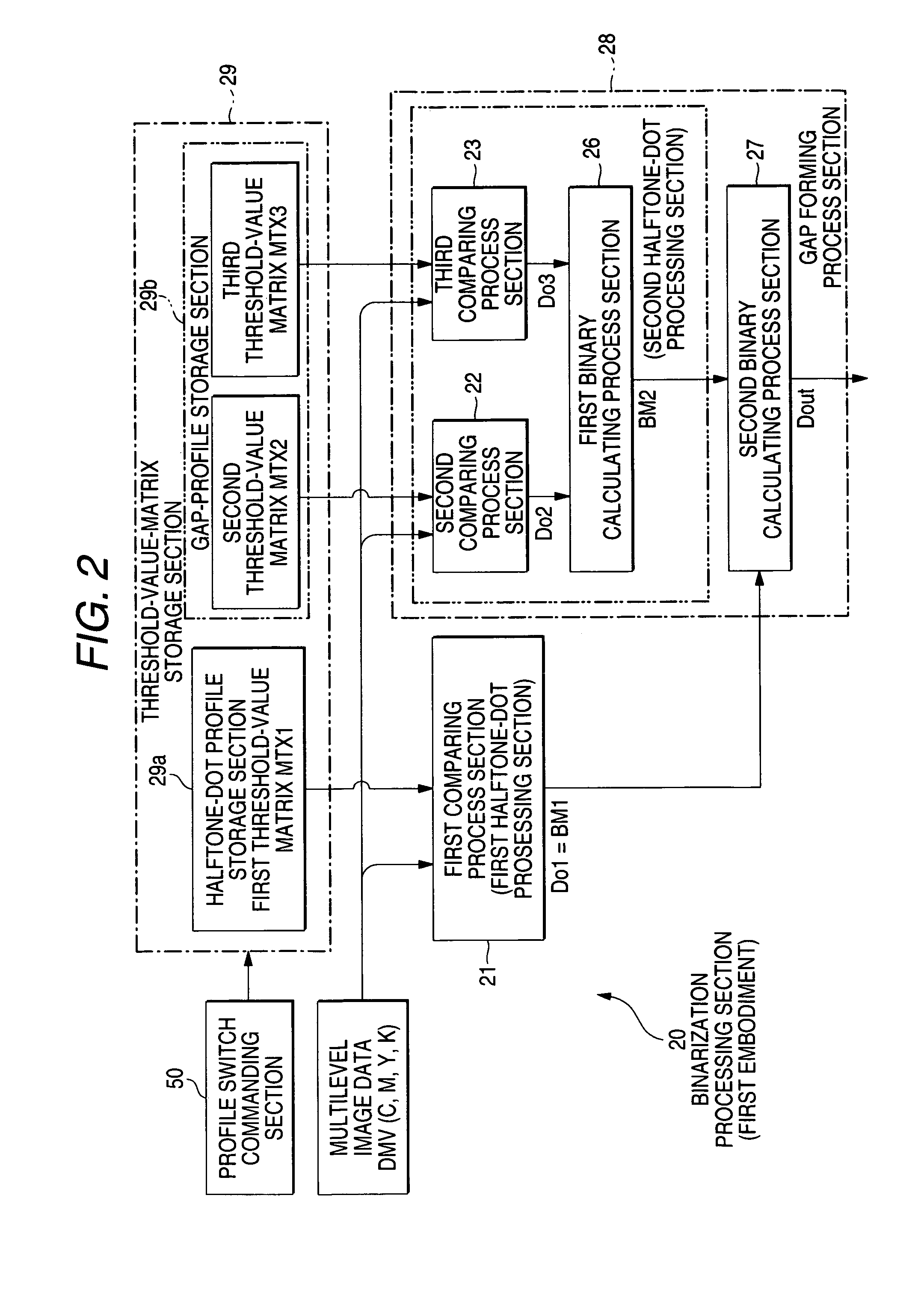
[0056]The binarization processing section 20 has features that it includes a plurality of sets of comparators for binarization and threshold-value matrixes, and that a plurality of calculation processors for performing a logic operation for binary data output from the comparators, as compared with conventional examples. In addition, the respective sets of the comparators for binarization and the threshold-value matrixes are modules, which can form the same halftone-dot structures, but are characterized by the values of the threshold-value matrixes.

[0057]Specifically, as shown in the figure, the binarization processing section 20 according to the first embodiment includes three comparing sections 21, 22 and 23 for performing a comparison process for binarization by referring to the multilevel data to be processed and the threshold-value matrix, two binary calculating process sections 26 and 27 for performing a logic operation for binary data output from the comparing sections 21, 22...

second embodiment

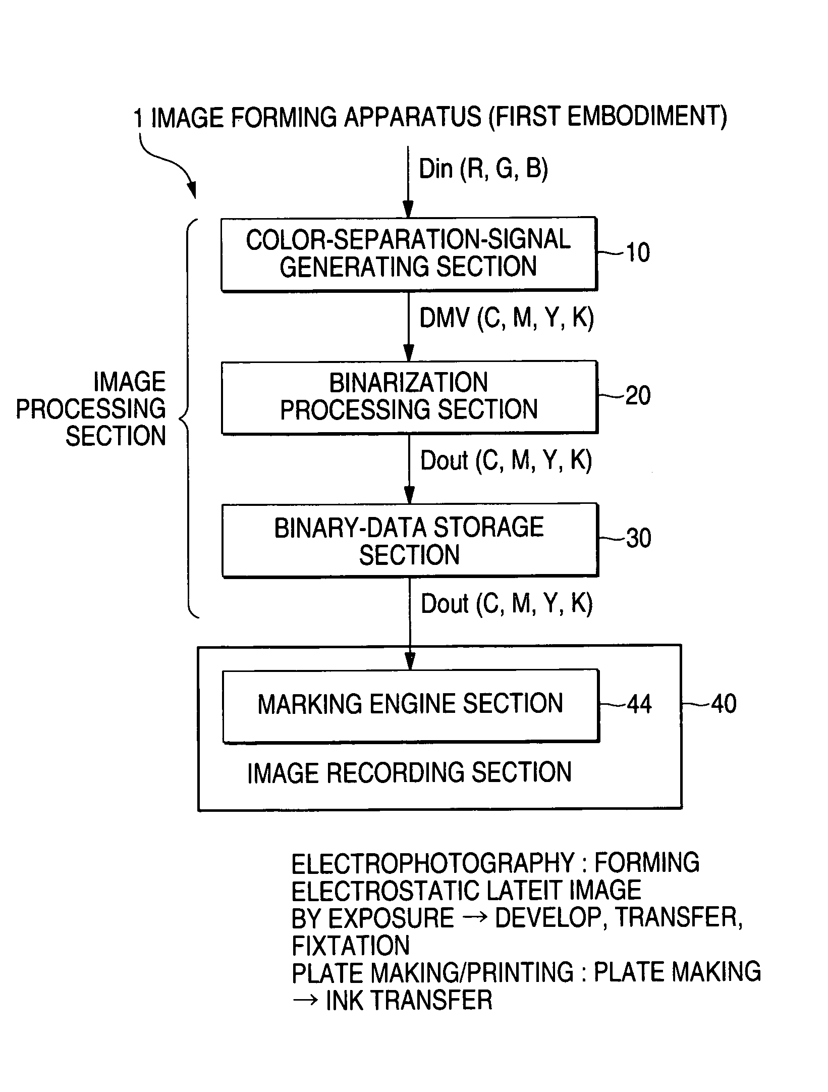
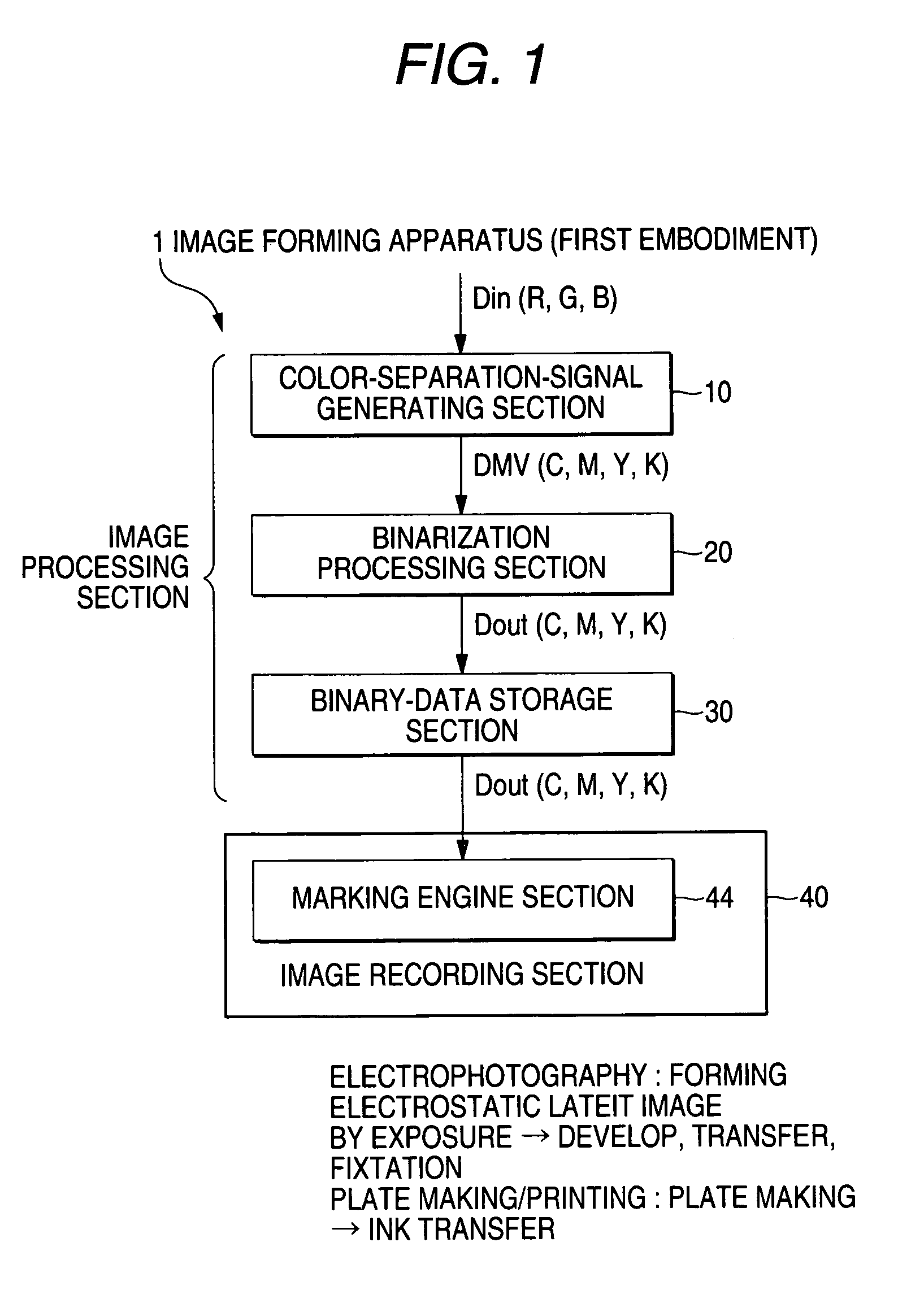
[0111]Specifically, as shown in FIG. 9, an image forming apparatus 1 includes a color-separation-signal generating section 10, a binarization processing section 60, a binary-data storage section 30, and an image recording section 70.

[0112]Even though not shown, the binarization processing section 60 of the second embodiment has a configuration in which the second binary calculating process section 27 in the binarization processing section 20 of the first embodiment is removed.

[0113]The image recording section 70 has a modulation controlling section 72 for generating output modulation data DEX for recording and a marking engine 74 for performing an image recording process on the basis of the output modulation data DEX generated by the modulation controlling section 72.

[0114]The binarization processing section 60 provides the first bitmap data BM1 (the first binary data Do1) output from the first comparing process section 21 to an on / off control input terminal 72a of the modulation c...

third embodiment

[0140]By changing parameters of the FIGS. 14(B), (C) and (D), the third embodiment can be applied as shown in the image example of the second example, unlike the image example of the first example. In this second example, if the multilevel image data DMV takes lower density (in this case, 12.5% to 15%), gap exists in the line structure. However, if the multilevel image data DMV takes further higher density and is in a predetermined density range (in this example, 50% to 75%), it is maintained that the non-output dots are in an isolated state. That is, it is possible that the non-output dots are not continued in the line-shaped halftone dot.

[0141]In this case, unlike the first example, the non-output dots (gap) having a size to some extent can be generated surely even on the high-density side. Therefore, even in the case where the number of screen lines becomes large, the phenomenon that the gap becomes narrow on the high-density side can be prevented by maintaining the non-output do...


PUM


Abstract

An image processing method generates a halftone-dot image by forming a halftone dot, which is represented by a set of one or plural output dots and corresponds to an intensity of an input image signal, while making a part of the dots constituting the halftone dot to be an actual non-output dot so as to reduce an amount of a coloring material of the halftone-dot portion. When the intensity of the image signal exceeds a predetermined value and is in a predetermined range, while maintaining contour dots, which are output dots contribute to formation of a contour of the halftone dot, to be the output dot, the image processing method makes a part of dots inside the contour dots to be the actual non-output dot.

Description

[0001]The entire disclosures of Japanese Patent Application No. 2005-45107 filed on Feb. 22, 2005 and Japanese Patent Application No. 2006-32016 filed on Feb. 9, 2006, including the specifications, claims, drawings and abstracts are incorporated herein by reference in its entirety.BACKGROUND OF THE INVENTION[0002]1. Field of the Invention[0003]The present invention relates to an image processing method, an image processing apparatus, and an image forming apparatus. More specifically, the invention relates to a binarization processing technique for generating a halftone-dot image by forming a halftone dot having a predetermined size corresponding to an intensity of an input image signal, the halftone dot which is used to record a halftone-dot image on an image recording medium in a printing technique such as an electrophotographic method and an inkjet method.[0004]2. Description of the Related Art[0005]As one of the techniques for generating a halftone-dot image using binary data, th...

Claims


Application Information

Patent Timeline
Patent Type & Authority Patents(United States)
IPC IPC(8): G06K15/00
CPCH04N1/4055
Inventor ISHII, AKIRATAKEBE, YOSHIFUMI
Owner FUJIFILM BUSINESS INNOVATION CORP
Why Eureka
Try Eureka