

Halftone Dot formation Method and Apparatus for Reducing Layer Thickness of Coloring Material Inside Halftone Dots, and Image Formation Apparatus
a technology of halftone dots and coloring materials, which is applied in the field of image processing methods, image processing apparatuses, and image forming apparatuses, can solve the problems of difficult compatibility of the amount of toner needed for the maximum density, high possibility of this problem, and excessive amount of toner for halftone reproduction, so as to achieve effective thinning of the halftone-dot portion, reduce the thickness of the coloring material inside the halftone dot, and achieve the effect of reducing the quality
- Summary
- Abstract
- Description
- Claims
- Application Information
AI Technical Summary
Benefits of technology
Problems solved by technology
Method used
Image

Examples
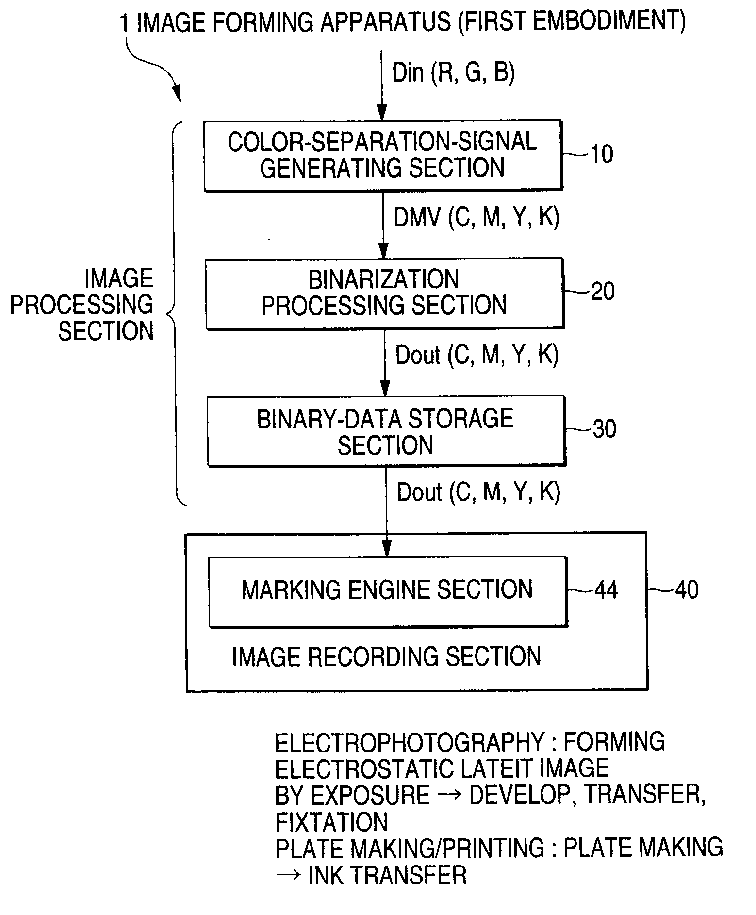
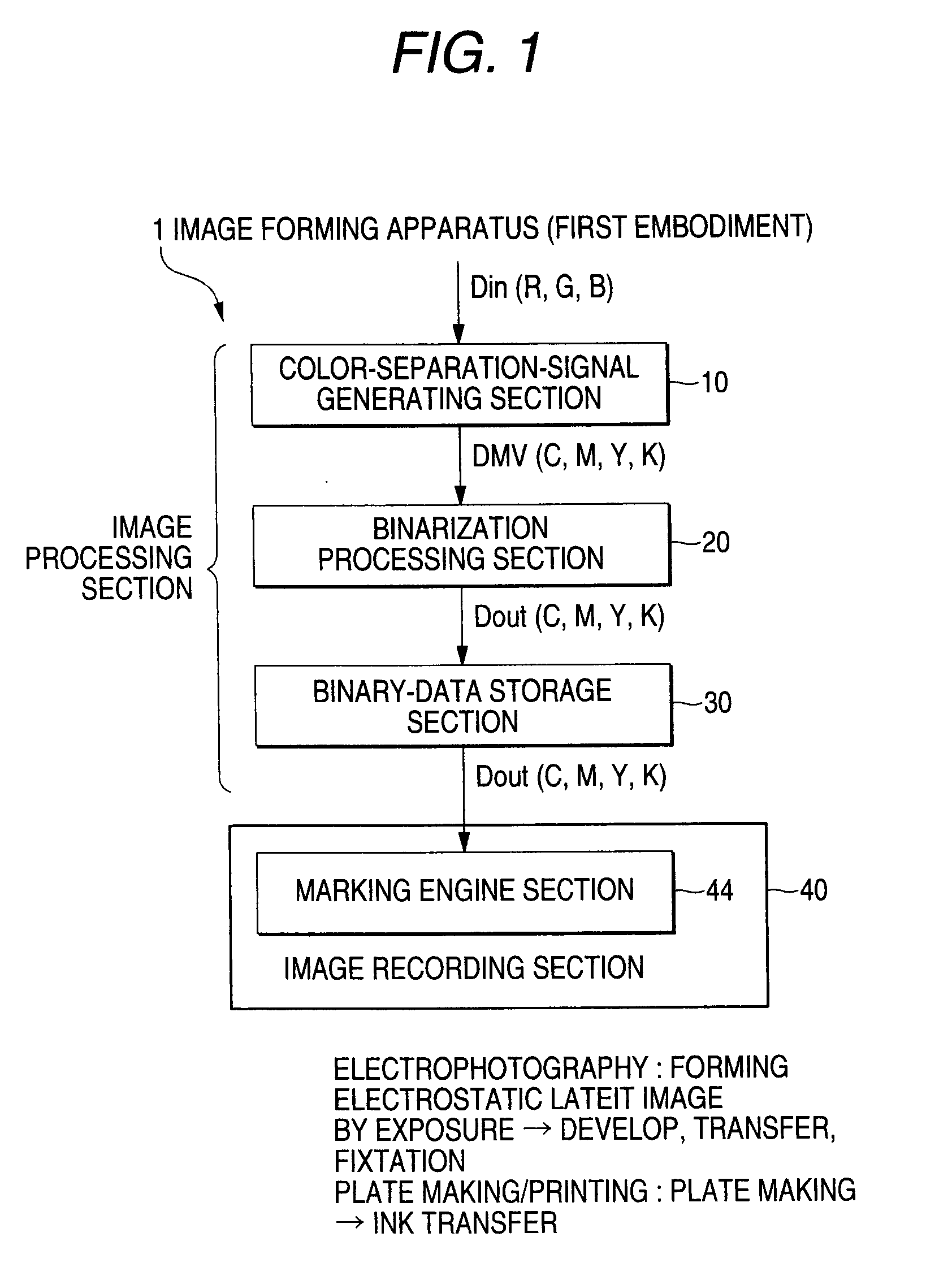
first embodiment
Procedure of the Halftone-Dot Process
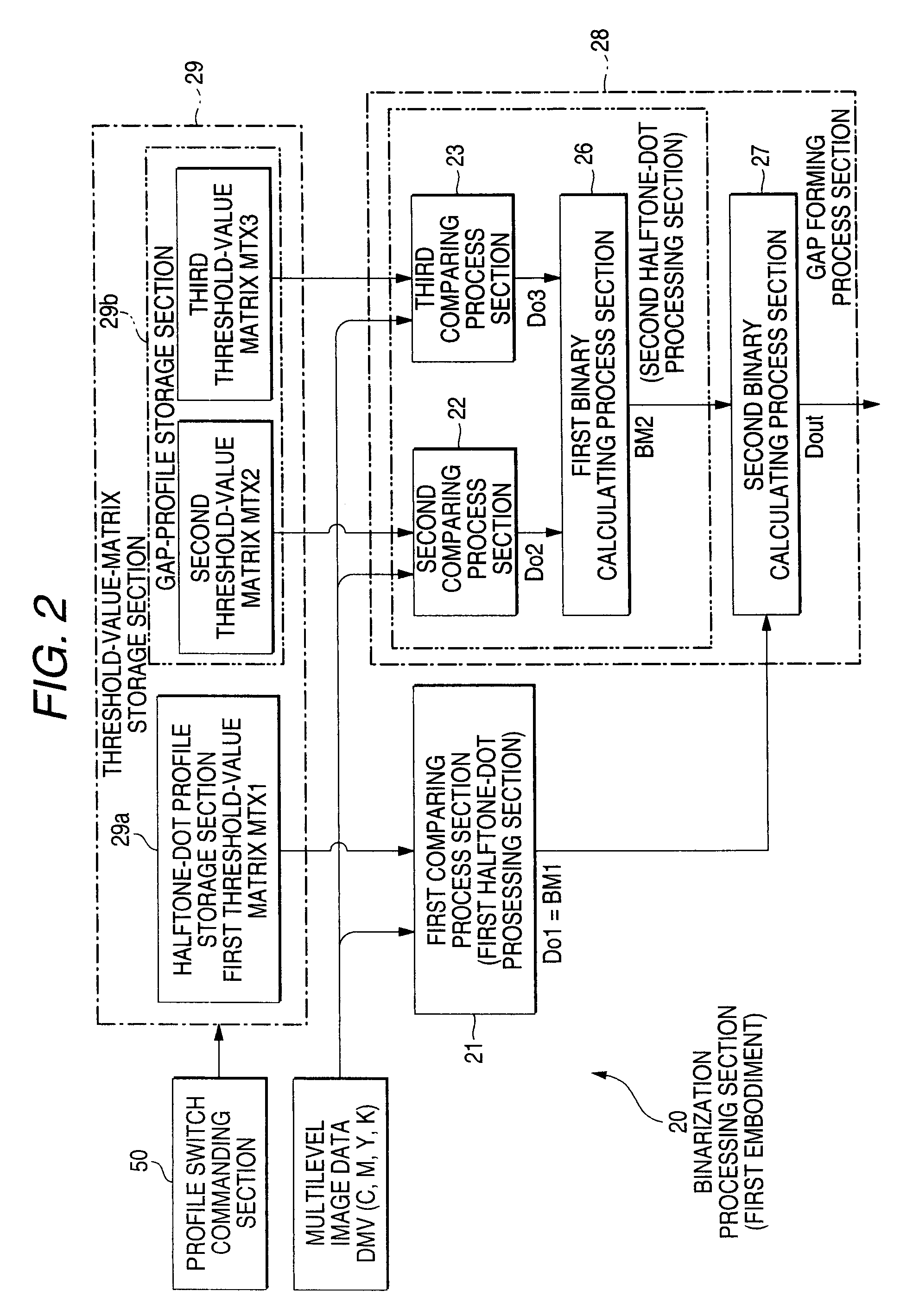
[0081]FIG. 5 and FIGS. 6(A) to 6(E) are diagrams illustrating the binarization process (specifically, halftone-dot process) executed in the binarization processing section 20 according to the first embodiment. Here, in the case where the binarization processing section 20 forms non-output dot with the dot-shaped halftone dot (dot screen) being a process target, the following description will be given by assuming that the gap-profile storage section 29b stores the gap-size profile data of the gap-size variable system shown in FIG. 3(B).
[0082]FIG. 5 is a flow chart illustrating an outline of a process of the halftone-dot process by the binarization processing section 20 according to the first embodiment. FIGS. 6(A) to 6(E) are diagrams illustrating a process of generating ring-shaped halftone dots according to the halftone-dot process performed by the binarization processing section 20 of the first embodiment. For example, FIG. 6(A) shows an exampl...
second embodiment
Procedure of the Halftone-Dot Process
[0118]FIG. 10 and FIGS. 11(A) to 11(D) are diagrams illustrating a binarization process (specifically, halftone-dot process) in the image forming apparatus according to the second embodiment. Here, it is assumed that the marking engine 74 employs the electrophotographic method.
[0119]FIG. 10 is a flow chart illustrating an outline of a procedure of the halftone-dot process executed by the image forming apparatus 1 according to the second embodiment. FIGS. 11(A) to 11(D) are diagrams illustrating steps for generating ring-shaped halftone dots according to the halftone-dot process executed by the image forming apparatus 1 of the second embodiment. For example, FIG. 11(A) shows an example of the first binary data Do1 output from the first comparing process section 21, that is, the first bitmap data BM1. FIG. 11(B) shows an example of the second binary data Do2 output from the second comparing process section 22. FIG. 11(C) shows an example of the thi...
third embodiment
; Basic
Halftone-Dot Processing Procedure
[0130]FIGS. 13 and 14 are diagrams showing binarization processing of a third embodiment (specifically, a halftone-dot processing). The binarization processing of the third embodiment has a feature in that what has a line-shaped halftone dot (line screen) as its original halftone-dot structure is taken as a process target, and the binarized processing section 20 generates non-output dots in accordance with a predetermined rule.
[0131]Here, FIG. 13 is diagram illustrating a line-shaped halftone dot (line screen), and FIG. 14 is a diagram illustrating a process of generating a non-output dot (gap) with respect to the line-shaped halftone dot. FIGS. 14(A) to (E) correspond to FIGS. 6(A) to 6(E), respectively.
[0132]In the process of generating the line-shaped halftone dot, a comparator compares input multilevel data, which is the process target (see FIG. 13(A)) and a threshold-value matrix for the line-shaped halftone dot (see FIG. 13(B)) as shown ...
PUM
 Abstract
Description
Claims
Application Information