Elevating machine control apparatus

a control apparatus and elevating machine technology, applied in the direction of dynamo-electric converter control, elevator, motor/generator/converter stopper, etc., can solve the problems of increasing cost and complicated device configuration, and achieve the effect of low cost and easy detection of failur

Inactive Publication Date: 2011-02-08
FUJITEC CO LTD
View PDF18 Cites 8 Cited by
  • Summary
  • Abstract
  • Description
  • Claims
  • Application Information

AI Technical Summary

Benefits of technology

[0012]The elevating machine control apparatus of the present invention can extremely easily detect an on failure of the regenerating semiconductor device only by software without addition of a special device. The power generation braking resistor can be therefore prevented from being overheated at extremely low costs by incorporating the software in the control circuit for the inverter control.

Problems solved by technology

If a failure of the regenerating semiconductor device 12 remaining on and not returning off, i.e. an on failure occurs, then the power generation braking resistor 13 can be overheated and cause a fire.
However, because all of the approaches are to detect an occurrence of on failure using hardware, there has been a problem in that the additional provision of hardware makes the device configuration complicated and also increases the cost.

Method used


Image

  • Elevating machine control apparatus
  • Elevating machine control apparatus
  • Elevating machine control apparatus

Examples


Embodiment Construction

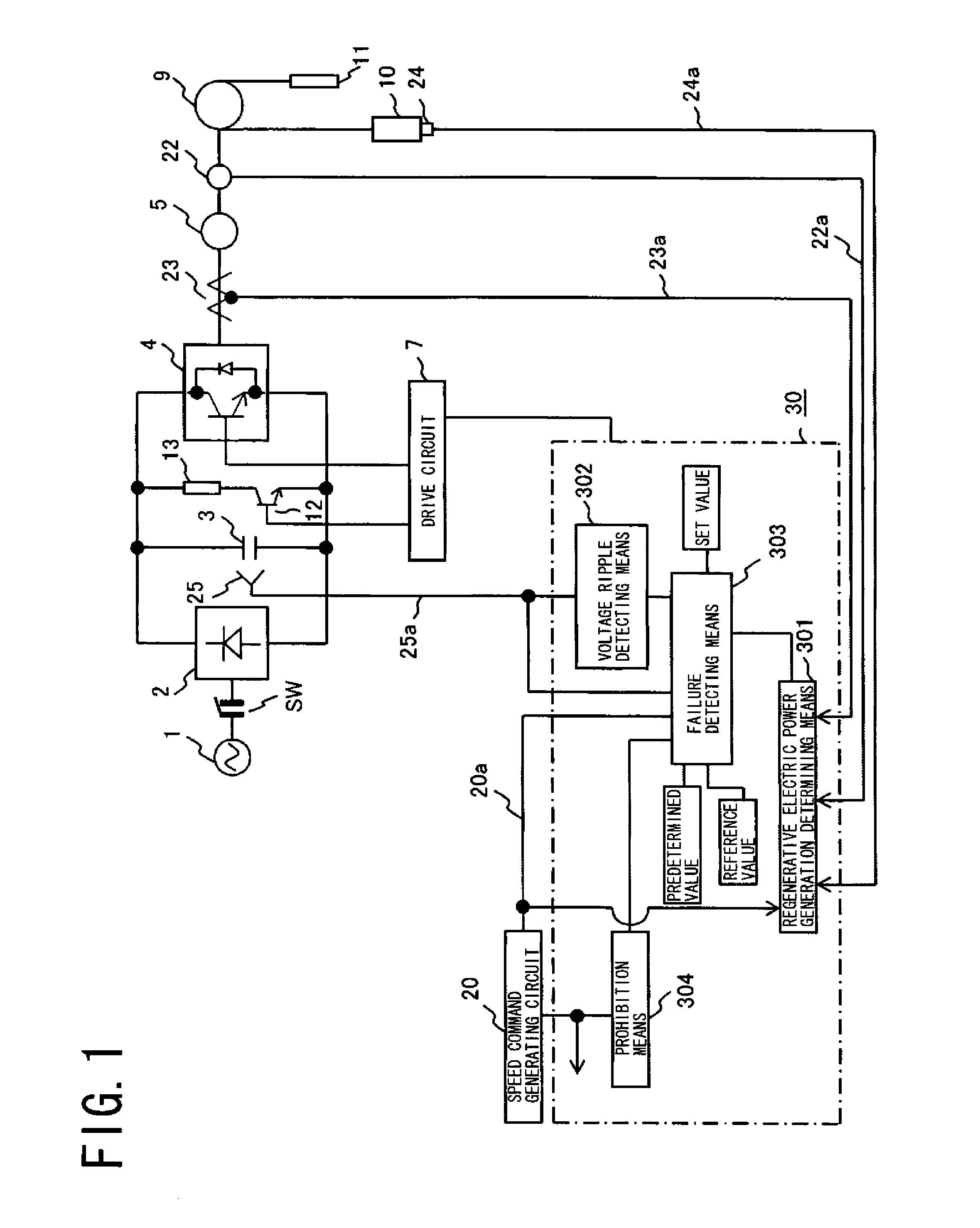
[0018]An elevator control apparatus embodying the present invention will be specifically described below with reference to the drawings. In FIG. 1, the same components as in FIG. 3 are provided with the same reference numerals as in FIG. 3.

[0019]As shown in FIG. 1, a three-phase alternating current from a commercial power supply 1 is input into a rectifier circuit 2 through a power supply interrupting electromagnetic contactor SW, full-wave rectified by the rectifier circuit 2, and converted to a direct current by a smoothing capacitor 3 further absorbing its ripple component. This converted direct current is converted by an inverter 4 to an alternating current of predetermined frequency, and input into an AC motor 5. A torque command from a controller 30 including a microcomputer is input into a drive circuit 7, and the drive circuit 7 controls the conduction width of a semiconductor device included in the inverter 4.

[0020]A heat dissipation circuit including a regenerating semicon...


PUM


Abstract

An elevating machine control apparatus controls an inverter (4) to drive an AC motor (5) connected to the inverter (4) with AC power, and energizes a power generation braking resistor (13) to apply a brake during regenerative operation of the AC motor (5). The apparatus prohibits the elevating machine from starting operating and interrupts power supply to the power generation braking resistor (13) if the DC stage voltage of the inverter (4) has a ripple quantity of a set value or more when the elevating machine is being stopped. Alternatively, the apparatus commands the elevating machine to stop operating and interrupts power supply to the power generation braking resistor (13) if the DC stage voltage of the inverter (4) during regenerative operation is a reference value or less when the elevating machine is in operation.

Description

TECHNICAL FIELD[0001]The present invention relates to a control apparatus that drives an elevating machine such as an elevator or escalator.BACKGROUND ART[0002]As shown in FIG. 3, an elevator conventionally includes an elevator cage 10 tied to a balance weight 11 with a rope wound around a sheave 9. An AC motor 5 drives the sheave 9 to hoist the elevator cage 10. The illustrated control apparatus drives the AC motor 5. In the control apparatus, a three-phase alternating current from a commercial power supply 1 is full-wave rectified by a rectifier circuit 2, and converted to a direct current by a smoothing capacitor 3 further absorbing its ripple component. This converted direct current is converted by an inverter 4 to an alternating current of predetermined frequency, and input into the AC motor 5. The inverter 4 includes a plurality of semiconductor devices. A torque command from a controller 6 is input into a drive circuit 7, and the drive circuit 7 controls the conduction width ...

Claims


Application Information

Patent Timeline
Patent Type & Authority Patents(United States)
IPC IPC(8): B66B1/28
CPCB66B1/308Y02B50/24Y02B50/00B66B5/02B66B25/00B66B1/30
Inventor OKADA, TAKAO
Owner FUJITEC CO LTD
Why Eureka
Try Eureka