Lamp unit for vehicles

a technology for lamps and vehicles, applied in vehicle interior lighting, transportation and packaging, light and heating equipment, etc., can solve the problems of reducing the depth dimension in the horizontal direction, not meeting the existing lamp unit for vehicles cannot meet the demands of reducing the depth dimension, so as to reduce the number of members and reduce manufacturing costs. , the effect of good utilization efficiency

Inactive Publication Date: 2011-02-08
ICHIKOH IND LTD
View PDF13 Cites 7 Cited by
  • Summary
  • Abstract
  • Description
  • Claims
  • Application Information

AI Technical Summary

Benefits of technology

[0019]The lamp unit for vehicles according to the present invention (Solution 1 of the present invention) is the one in which the planar reflect surface is arranged between the projection lens and its focus in such a way that the planar reflect surface intersects the light axis of the projection lens, as a result of which, at the symmetrical position with respect to the planar reflect surface by way of the planar reflect surface, the lens focus of the projection lens exists as a fictitious lens focus positioned at the second focus of the ellipse reflect surface, and the horizontal lens light axis of the projection lens exists as the fictitious light axis of the lens that is vertical and intersects the light axis of the lens orthogonally by way of the planar reflect surface, the fictitious light axis of the lens being consistent with the light axis of the ellipse reflect surface. Therefore, in the lamp unit for vehicles according to the present invention (Solution 1 of the present invention), the projection lens and the planar reflect surface can be arranged in the horizontal direction, and the projection lens, the planar reflect surface, the reflector, the semiconductor light source, and the shade are arranged in the vertical direction, and thus the lamp unit for vehicles according to the present invention (Solution 1 of the present invention) can reduce the depth dimension in the horizontal direction and the height dimension in the vertical direction, and can meet the demands for reducing the depth dimension and the height dimension.
[0027]Furthermore, because, in the lamp unit for vehicles according to the present invention (Solution 5 of the present invention), the planar reflect surface and the shade are formed integratedly, and the reflector and the light shutout member are formed integratedly, the number of the members can be reduced, and the manufacturing cost can be reduced. Furthermore, because, in the lamp unit for vehicles according to the present invention (Solution 5 of the present invention), the planar reflect surface for forming the fictitious focus of the projection lens and the shade for forming the cutoff line of the predetermined distributed light pattern are formed integratedly, the precision of the predetermined distributed light pattern having the cutoff line can be improved. Furthermore, because, in the lamp unit for vehicles according to the present invention (Solution 5 of the present invention), the reflector of the first reflect surface and the light shutout member for enabling the reflected light from the first reflect surface to illuminate toward the planar reflect surface are formed integratedly, the reflected light from the first reflect surface can illuminate reliably toward the planar reflect surface, and the light distributed is not lost and can be used effectively

Problems solved by technology

Because of this reason, the existing lamp unit for vehicles can not meet the demands for reducing the depth dimension.
Therefore, because, in this type of lamp unit for vehicles, the electricity discharge lamp bulb, the reflector, and the projection lens, and the planar reflect surface are arranged in the direction of the front and the rear of the vehicle, the depth dimension in the horizontal direction becomes big, just as the lamp unit for vehicles mentioned in Patents 1-3, and it can not meet the demands for reducing the depth dimension.
However, this type of existing lamp unit for vehicles is not the projector type of lamp unit for vehicles that does not use projection lens.
And moreover, because this type of existing lamp unit for vehicles is the one in which the light axis of the first reflector intersects the light axis of the second reflector, the height dimension in the vertical direction increases at the same time the depth dimension in the horizontal direction reduces, and thus it can not meet the demands for reducing the depth dimension and the height dimension.
Furthermore, the existing lamp unit for vehicles mentioned above do not take into consideration the method of preventing the light, except the predetermined distributed light pattern projected from the projection lens, from emitting from the projection lens, and therefore, there exists the circumstance where the light except the predetermined distributed light pattern projected from the projection lens, i.e. the light not distributed, emits from the projection lens.
In addition, the existing lamp unit for vehicles mentioned above do not take into consideration the method of the effective use of the light from semiconductor light source, and therefore, the existing lamp unit for vehicles mentioned above do not effectively use the light from semiconductor light source.

Method used


Image

  • Lamp unit for vehicles
  • Lamp unit for vehicles
  • Lamp unit for vehicles

Examples


embodiment 1

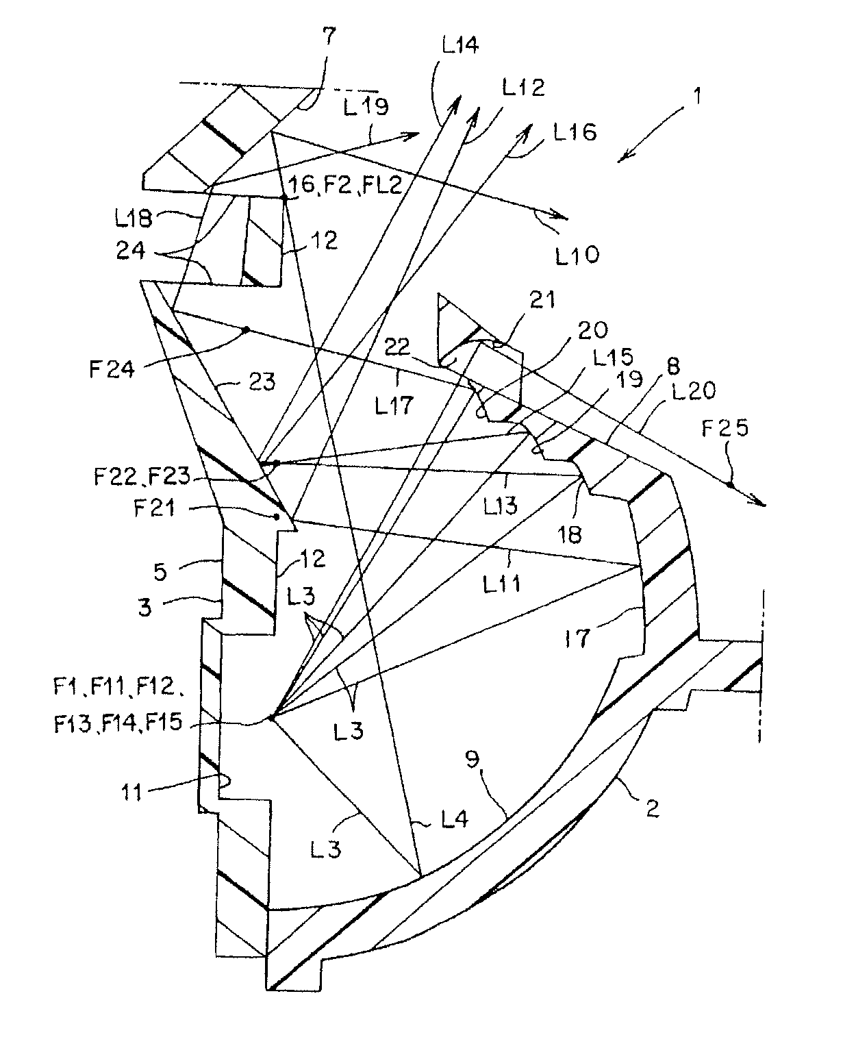
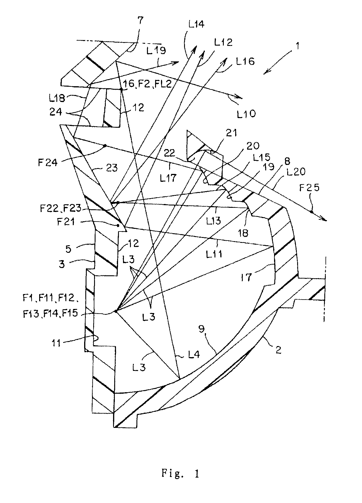
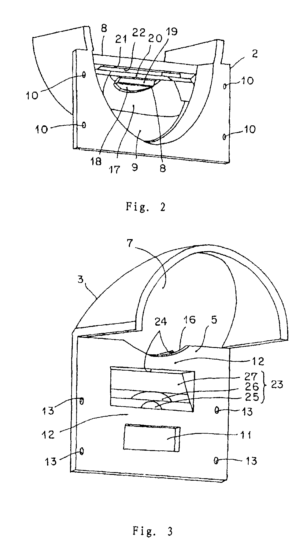
[0041]FIG. 1-FIG. 7 illustrate Embodiment 1 of the lamp unit for vehicles according to the present invention. The explanation of the structure of the lamp unit for vehicles of the Embodiment 1 is now given. In the figures, mark 1 is the lamp unit for vehicles in Embodiment 1 which is, for example, the head lamp of the vehicle. The lamp unit for vehicles mentioned here comprises a first reflector 2 (a main reflector, a light shutout member and concurrently a reflector) on the front side, a second reflector 3 (a subreflector, a shade and concurrently a reflector) on the rear side, a semiconductor light source 4, a shade 5, a projection lens 6 (a convex lens, spotlight lens), a planar reflect mirror 7, heat sink member (not shown), a light shutout member 8, a lamp housing and a lamp lens not shown (for example, a transparent outer lens, etc.).

[0042]The first reflector 2, the second reflector 3, the semiconductor light source 4, the shade 5, the projection lens 6, the planar reflect mir...

embodiment 2

[0089]FIG. 8 and FIG. 9 illustrate the second embodiment of the lamp unit for vehicles according to the present invention. In the figures, the same marks as those in FIG. 1-FIG. 7 indicate the same components. The explanation of Embodiment 2 of the lamp unit for vehicles 1A according to the present invention is now given.

[0090]In the lamp unit for vehicles 1A in Embodiment 2, in the first supplemental reflect surface, the second focus of the second part 18, the second focus of the third part 19, and the second focus of the fourth part 20 are the focus 26 in common or roughly in common. On the other hand, in the second supplemental reflect surface, the reflect surface in common 28 is arranged at the focus 26 in common or its vicinity. The reflect surface in common 28 of the second supplemental reflect surface is formed with an ellipse reflect surface, or other flexible reflect surface, or a planar reflect surface.

[0091]Because the lamp unit for vehicles 1A in Embodiment 2 is structur...

embodiment 3

[0093]FIG. 10-FIG. 12 illustrate the third embodiment of the lamp unit for vehicles according to the present invention. In the figures, the same marks as those in FIG. 1-FIG. 9 indicate the same components. The explanation of Embodiment 3 of the lamp unit for vehicles 1B according to the present invention is now given.

[0094]In the lamp unit for vehicles 1B in Embodiment 3, the light shutout member 8 is provided with a first supplemental reflect surface 29 for reflecting the light L3 from the semiconductor light source 4 toward the predetermined direction. As shown in FIG. 1, the first supplemental reflect surface 29 is formed with an ellipse reflect surface, and has a first focus F17 positioned at the first focus F1 or it vicinity of the first reflect surface 9 and a second focus F27 positioned above the first focus F17. On the other hand, the shade 5 is provided a second supplemental reflect surface 30 positioned in the vicinity of the second focus F27. Furthermore, the second supp...


PUM


Abstract

In existing lamp unit for vehicles, the light from the semiconductor light source can not be effectively used. In the present invention, a planar reflect surface (7) is arranged between the projection lens (6) and its focus (FL1) in such a way that the planar reflect surface (7) intersects the light axis (Z1-Z1) of the projection lens (6); a light shutout member (8) is arranged between the semiconductor light source (4) and the projection lens (6); the light shutout member (8) is provided with supplemental reflect surfaces (17-20) reflecting the light (L3) from the semiconductor light source (4) toward the shade (5). As a result, the light (L3) from the semiconductor light source (4) can be effectively used.

Description

FIELD OF THE INVENTION[0001]The present invention relates to a projector type of lamp unit for vehicles using a semiconductor light source, for example LED and the like, as a light source, especially to a lamp unit for vehicles that can be used as a vertical projector lamp whose depth dimension and height dimension can be miniaturized, can prevent the light except the predetermined distributed light pattern projected from a projection lens, i.e. the light not distributed, from emitting from the projection lens, and can effectively use the light from the semiconductor light source.BACKGROUND OF THE INVENTION[0002]There exists the type of lamp unit for vehicles (for example, Patent 1, Patent 2, and Patent 3). The explanation of the existing lamp unit for vehicles is given now. The existing lamp unit for vehicles includes a reflector having an ellipse reflect surface, a semiconductor light source, for example LED and the like, arranged in such a way that its light emitting part is posi...

Claims


Application Information

Patent Timeline
Patent Type & Authority Patents(United States)
IPC IPC(8): B60Q1/00
CPCF21S48/1159F21S48/1163F21S48/137F21S48/1388F21S48/145F21S41/143F21S41/255F21S41/321F21S41/333F21S41/43F21S41/365F21W2102/18F21S41/336F21S41/155
Inventor NISHIHATA, KOJI
Owner ICHIKOH IND LTD
Why Eureka
Try Eureka