Backlight module

a backlight module and backlight technology, applied in the field of backlight modules, can solve the problems of high defect rate, and achieve the effect of uniform color ton

Active Publication Date: 2011-02-08
DYNASCAN TECH
View PDF3 Cites 17 Cited by
  • Summary
  • Abstract
  • Description
  • Claims
  • Application Information

AI Technical Summary

Benefits of technology

[0014]The primary objective of the present invention is to provide a backlight module with a palette device. By means of the palette device, the light source of the backlight module can be adjusted in order to produce the light with uniform color tone.

Problems solved by technology

Besides, the color coordinates of some light from some LEDs are too small so as to cause a condition of hard usage and that the color tone is closer to ashy, and then a defect rate is highly increased.

Method used


Image

  • Backlight module
  • Backlight module
  • Backlight module

Examples


Embodiment Construction

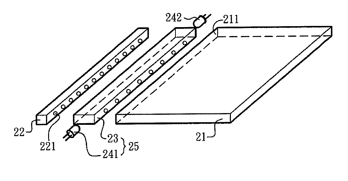
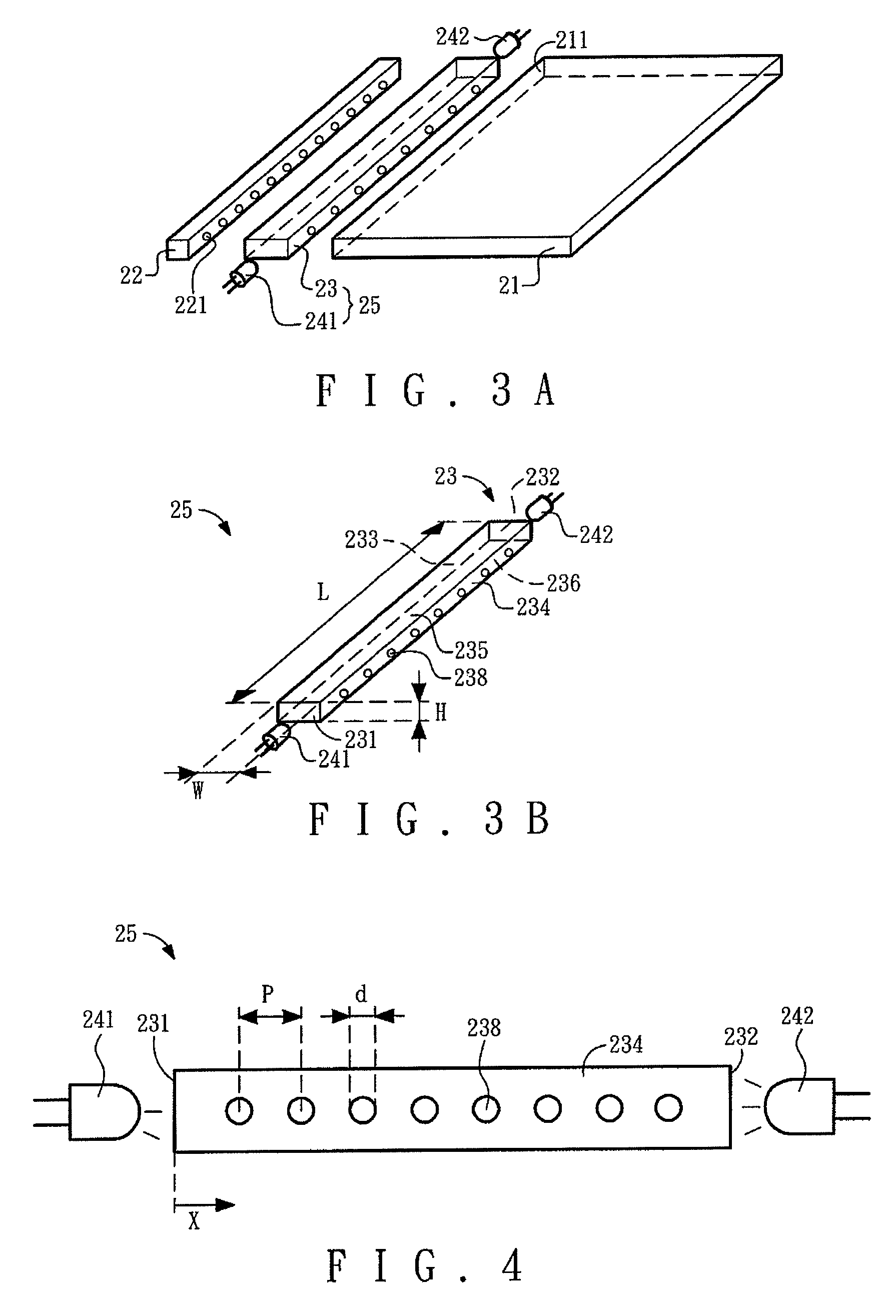
[0035]With references to FIG. 3A and FIG. 3B, which illustrate a schematic view of the backlight module of the present invention and a schematic view of a palette device of the backlight module of the present invention.

[0036]As shown in the figures, the backlight module adopts a side end thereof to be a role for inputting light. The backlight module includes a light-guide plate 21, a palette device 25 and an LED bar 22.

[0037]The light-guide plate 21 has a side end 211, which is a light incident end. The palette device 25 has a palette and light-guide bar 23 and a palette LED 241.

[0038]The palette and light-guide bar 23 is at least a hexahedral member, but can be a heptahedron, an octahedron or a polyhedron with more than eight surfaces as well. Preferably, the palette and light-guide bar 23 is a hexahedral member and has a light-input surface 233, a light-output surface 234 corresponding to the light-input surface 233, a first side 231, a second side 232 corresponding to the first s...


PUM


Abstract

A backlight module comprises at least a light-guide plate, a palette device and an LED bar. The palette device comprises a palette and light-guide bar and at least one palette LED. The palette and light-guide bar is disposed at a side end of the light-guide plate and has a light-input surface, a light-output surface corresponding to the light-input surface, a first side, a second side corresponding to the first side, a top, and a bottom corresponding to the top. The palette LED is adjacent to the first side and provides a palette light into the palette and light-guide bar. The LED bar is adjacent to the light-input surface of the palette and light-guide bar. The LED bar emits an incident light, which is through the light-input surface into the palette and light-guide bar, wherein a light mixed by the incident light and the palette light is output through the light-output surface is and the side end into the light-guide plate so as to be a light source of the backlight module.

Description

BACKGROUND OF THE INVENTION[0001]1. Field of the Invention[0002]The present invention generally relates to a backlight module, more particularly to a backlight module having a palette device.[0003]2. Description of the Prior Art[0004]A general display with the feature of autoluminescence as an LCD may need a backlight source for displaying images. For several prior backlight technologies, the backlight module with the feature of inputting light from a side end thereof may be more demanded to the needs of slim product. Such technologies are being widely applied to the screen of a laptop computer and an LCD.[0005]With references to FIG. 1 and FIG. 2, which illustrates a schematic view of a prior backlight module and a schematic view of a light-guide plate and an LED bar of the prior backlight module. As shown in the figures, a backlight module 10 includes a light-guide plate 11, an LED bar 12, a reflector 13, and a plurality of optical films 14. The light-guide plate 11 has a side end...

Claims


Application Information

Patent Timeline
Patent Type & Authority Patents(United States)
IPC IPC(8): F21V7/04
CPCG02F1/133615
Inventor WANG, TSUN-I
Owner DYNASCAN TECH
Why Eureka
Try Eureka