Driving arrangement for an OLED panel

a technology of driving arrangement and oled panel, which is applied in the direction of instruments, static indicating devices, etc., can solve the problems of higher voltage process and the cost of oled controller, and achieve the effect of enhancing the brightness and picture quality of the oled panel without increasing the cos

Inactive Publication Date: 2011-02-22
RICHTEK TECH
View PDF1 Cites 0 Cited by
  • Summary
  • Abstract
  • Description
  • Claims
  • Application Information

AI Technical Summary

Benefits of technology

With different voltage levels for the gate driver and the source driver, the driving arrangement of the present invention may produce a driving voltage higher than a wafer process voltage to drive the OLED panel, enhance the brightness and the picture quality of the OLED panel without increasing the cost, and adjust the maximum driving voltage for the OLED panel by defining the voltages provided by the power supply for the gate driver and the source driver.

Problems solved by technology

However, the OLED controller's cost depends on the wafer process.
A higher voltage process will have a higher cost.

Method used


Image

  • Driving arrangement for an OLED panel
  • Driving arrangement for an OLED panel
  • Driving arrangement for an OLED panel

Examples


Embodiment Construction

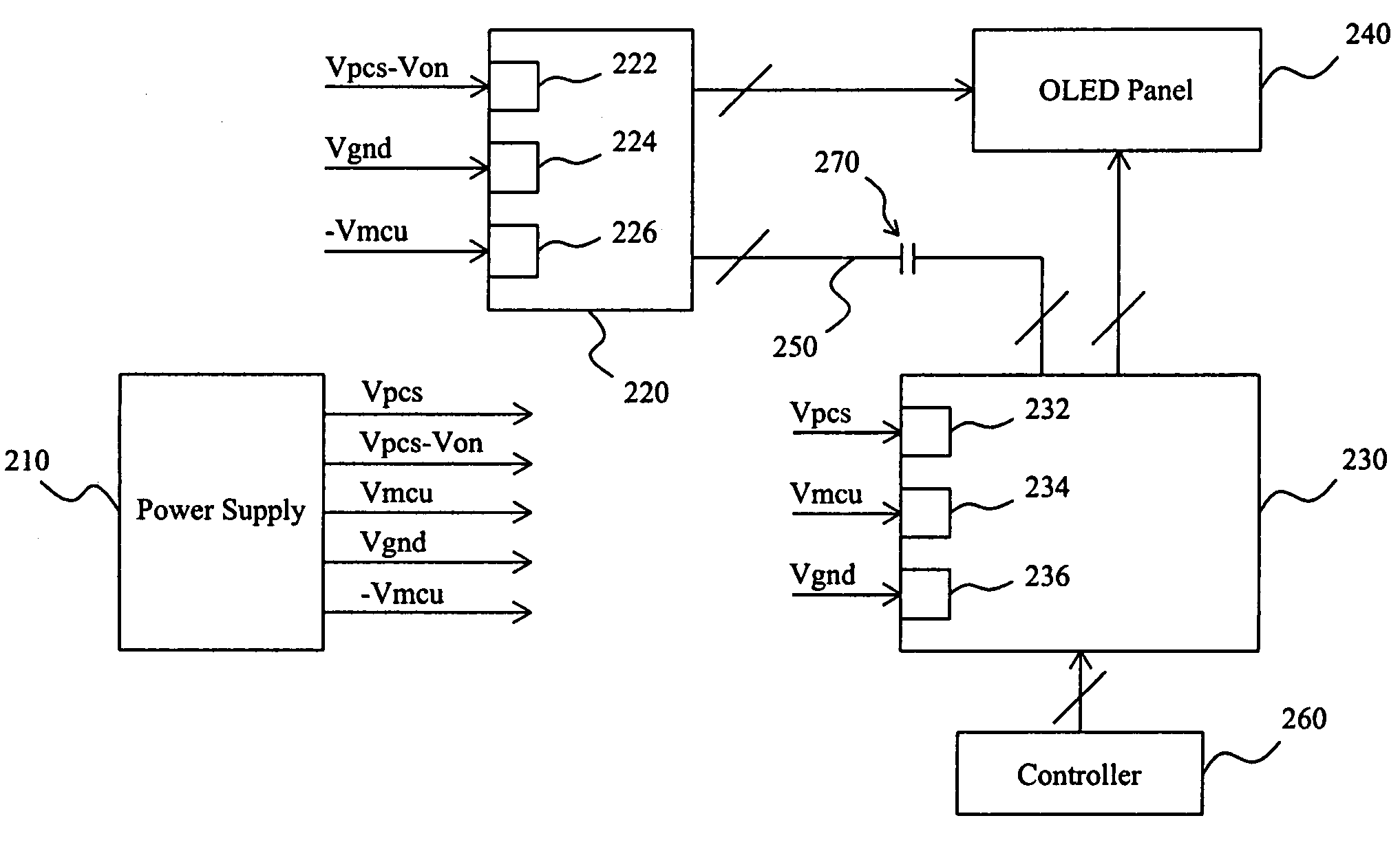
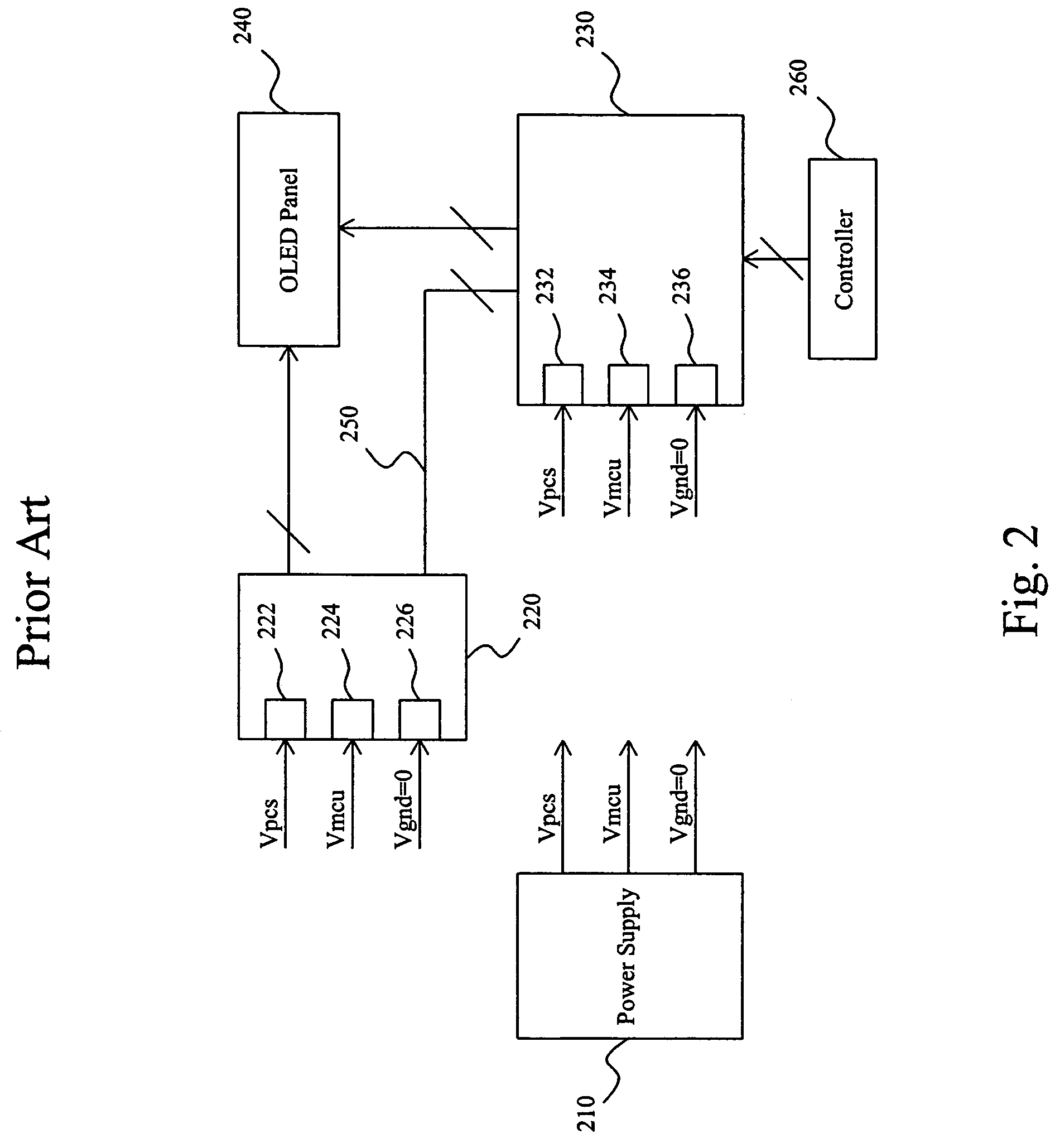
FIG. 3 shows an embodiment according to the present invention, in which the same reference numerals as used in FIG. 2 refer to the same elements, whereas they are differently configured. In this driving arrangement, power supply 210 provides the voltages Vpcs, Vpcs−Von, Vmcu, Vgnd, and −Vmcu required for gate driver 220 and source driver 230, the gate driver 220 has a high-voltage terminal 222, a low operation voltage terminal 224, and a ground terminal 226 connected with the voltages Vpcs−Von, Vgnd and −Vmcu respectively, and the source driver 230 has a high-voltage terminal 232, a low operation voltage terminal 234, and a ground terminal 236 connected with the voltages Vpcs, Vmcu and Vgnd respectively. Since the ground terminal 236 of the gate driver 220 receives the negative microcontroller operation voltage −Vmcu, instead of zero voltage, the difference between the high voltage and the low voltage of the gate driver 220, the voltage of the high-voltage terminal 222—the voltage o...


PUM


Abstract

In a driving arrangement for an OLED panel, by using different voltage levels for a gate driver and a source driver, a driving voltage higher than a wafer process voltage is produced for the OLED panel and therefore improves the picture quality.

Description

FIELD OF THE INVENTIONThe present invention is related generally to an organic light-emitting diode (OLED) display and, more particularly, to a driving arrangement for an OLED panel.BACKGROUND OF THE INVENTIONFIG. 1 is a diagram of picturing the relationship between the driving voltage and the brightness of an OLED. When an OLED in a panel is applied with a forward voltage higher than a turn-on voltage Von which depends on the panel process, it is turned on and the higher the driving voltage is, the brighter the OLED will be. If the driving voltage is lower than the turn-on voltage Von, either a forward voltage or a backward voltage, the OLED is dark. However, the OLED controller's cost depends on the wafer process. A higher voltage process will have a higher cost.For more detail, FIG. 2 shows a conventional driving arrangement for an OLED panel, in which power supply 210 may provide a wafer process voltage Vpcs, a microcontroller operation voltage Vmcu, and a ground voltage Vgnd fo...

Claims


Application Information

Patent Timeline
Patent Type & Authority Patents(United States)
IPC IPC(8): G09G3/30
CPCG09G3/3216
Inventor KU, CHIUNG-CHING
Owner RICHTEK TECH
Why Eureka
Try Eureka