
Key fob device and method

a key fob and key technology, applied in the field of key fobs, can solve the problems of difficult and expensive molding of a family of key fobs with different features, and achieve the effect of reducing additional costs

Inactive Publication Date: 2011-03-01
STRATTEC SECURITY +1
View PDF23 Cites 32 Cited by
  • Summary
  • Abstract
  • Description
  • Claims
  • Application Information

AI Technical Summary

Benefits of technology

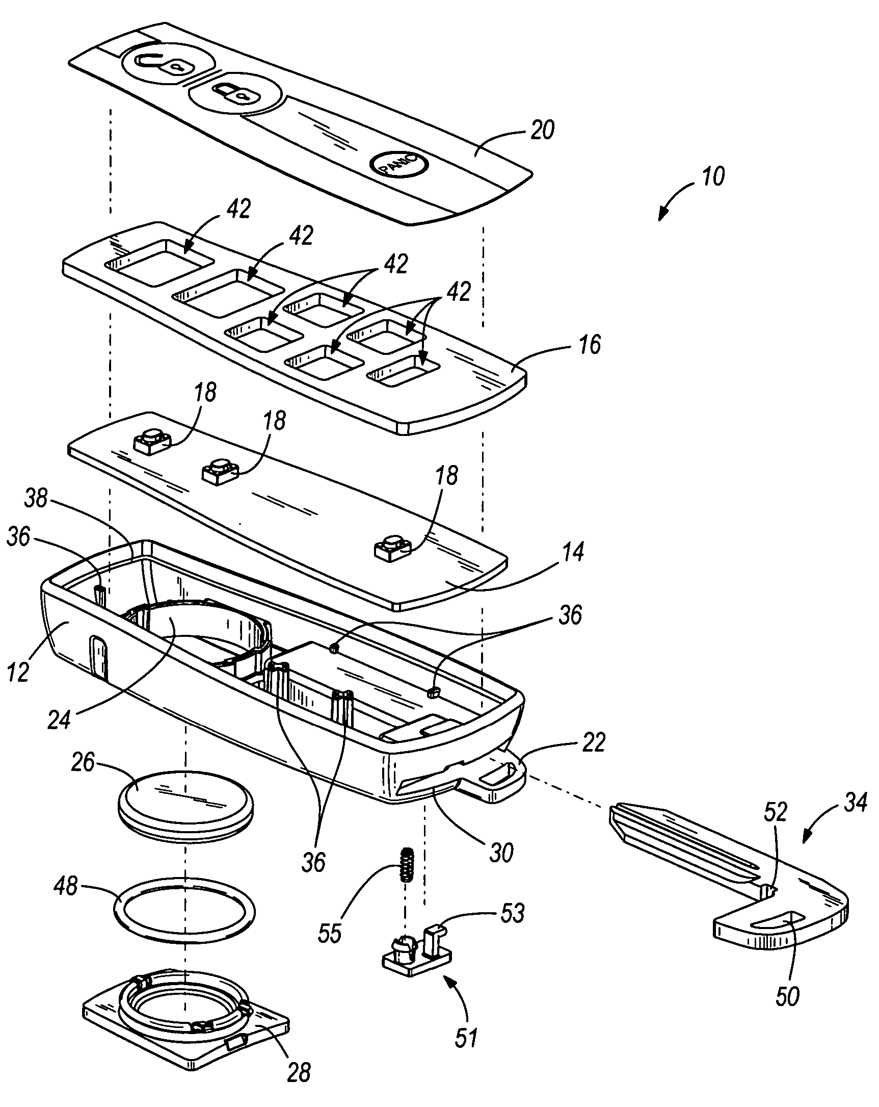
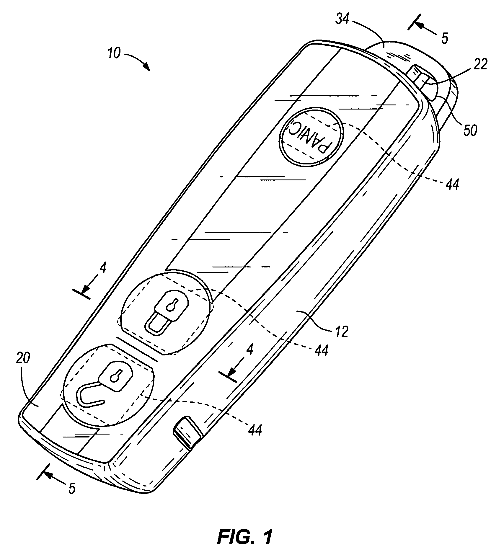
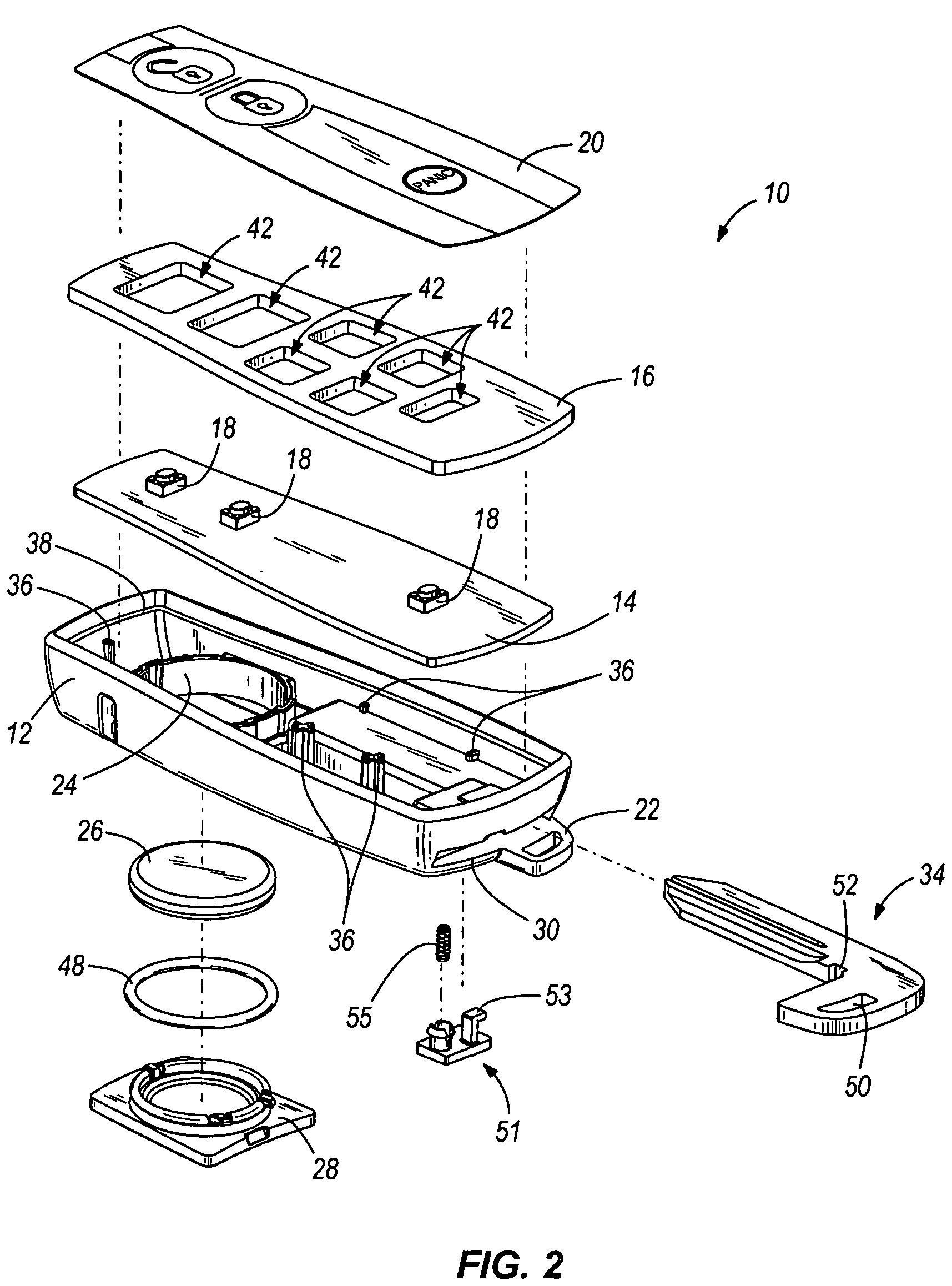
The patent text describes a way to add color and patterns to key fobs without adding much extra cost. It also allows for the creation of key fobs with different numbers of buttons depending on the vehicle and accessories. The key fob has a housing, a lid, and a flexible film with switches underneath. The flexible film can have stylized graphics for different vehicles. The method involves printing the graphics on a flexible film, positioning the circuit board in the housing, and attaching the flexible film to the lid. Overall, this invention allows for the creation of customizable key fobs with unique designs.

Problems solved by technology

Due to the cost of the additional tooling, molding a family of key fobs with different features and styling is difficult and expensive.

Method used


Image

  • Key fob device and method
  • Key fob device and method
  • Key fob device and method

Examples


Embodiment Construction

[0017]Before any embodiments of the invention are explained in detail, it is to be understood that the invention is not limited in its application to the details of construction and the arrangement of components set forth in the following description or illustrated in the following drawings. The invention is capable of other embodiments and of being practiced or of being carried out in various ways. Also, it is to be understood that the phraseology and terminology used herein is for the purpose of description and should not be regarded as limiting. The use of “including,”“comprising,” or “having” and variations thereof herein is meant to encompass the items listed thereafter and equivalents thereof as well as additional items. Unless specified or limited otherwise, the terms “mounted,”“connected,”“supported,” and “coupled” and variations thereof are used broadly and encompass both direct and indirect mountings, connections, supports, and couplings. Further, “connected” and “coupled”...


PUM

PropertyMeasurementUnit
flexibleaaaaaaaaaa
sizeaaaaaaaaaa
coloraaaaaaaaaa

Abstract

A device and method for a key fob. The key fob device can include a housing, a lid defining one or more apertures, a circuit board including one or more switches, and a flexible film coupled to the housing and / or the lid. The flexible film can include one or more contact surfaces and stylized graphics.

Description

BACKGROUND OF THE INVENTION[0001]Conventional key fobs generally include a two-piece housing, molded silicone rubber buttons, a printed circuit board (PCB), an antenna, and a battery clip coupled to one of the two pieces of the housing. To reduce costs, the pieces of the housing are generally made from black plastic. A single piece of molded silicone rubber (substantially the same size as the housing) generally defines each of the buttons and a lip around the rubber piece to provide a seal between the two pieces of the housing. Carbon pieces are generally attached to the undersides of the buttons. The PCB is positioned beneath the silicon rubber buttons and includes electrical traces. When a button is depressed, the carbon piece on the underside of the button closes the traces on the PCB and activates a desired feature on a vehicle.[0002]For a family of conventional key fobs, an entire family of tooling is required to accommodate varying numbers of buttons, patterns, textures, and o...

Claims


Application Information

Patent Timeline
Patent Type & Authority Patents(United States)
IPC IPC(8): H01H13/06
CPCE05B19/0082G07C9/00944H01H9/0235H01H2011/0093H01H2219/028Y10T29/49155H01H2223/003H01H2229/002H01H2229/02H01H2231/026H01H2231/032H01H2221/004
Inventor DIMIG, STEVEN J.
Owner STRATTEC SECURITY
Learn More