Safety switching apparatus and method for safely switching an electrical load on and off

a safety switch and electrical load technology, applied in electrical devices, relays, basic electric elements, etc., can solve the problems of preventing the ability of the activator to be switched, and achieve the effect of avoiding the risk of faulty short-term switching on, safe switching of an electrical load, and cost-effectiveness

Active Publication Date: 2011-03-01
PILZ (COMPANY)
View PDF16 Cites 10 Cited by
  • Summary
  • Abstract
  • Description
  • Claims
  • Application Information

AI Technical Summary

Benefits of technology

[0025]Secondly, the activation of the switching activator, for example a relay, is realized via the same current path in which the signaling element is also present. As a result, the switching activator is prevented from being capable of being switched on in an undesired manner for a short period of time.
[0054]In this way, on the one hand the configuration of the mode selection device can be carried out in a simple manner. Secondly, it is also possible, however, to carry out a plausibility check for the adjustment carried out. Thus, for example, a configuration process could be required prior to the first use of the electrical load, and this configuration process requires actuation of the signaling elements.

Problems solved by technology

As a result, the switching activator is prevented from being capable of being switched on in an undesired manner for a short period of time.

Method used


Image

  • Safety switching apparatus and method for safely switching an electrical load on and off
  • Safety switching apparatus and method for safely switching an electrical load on and off
  • Safety switching apparatus and method for safely switching an electrical load on and off

Examples


Embodiment Construction

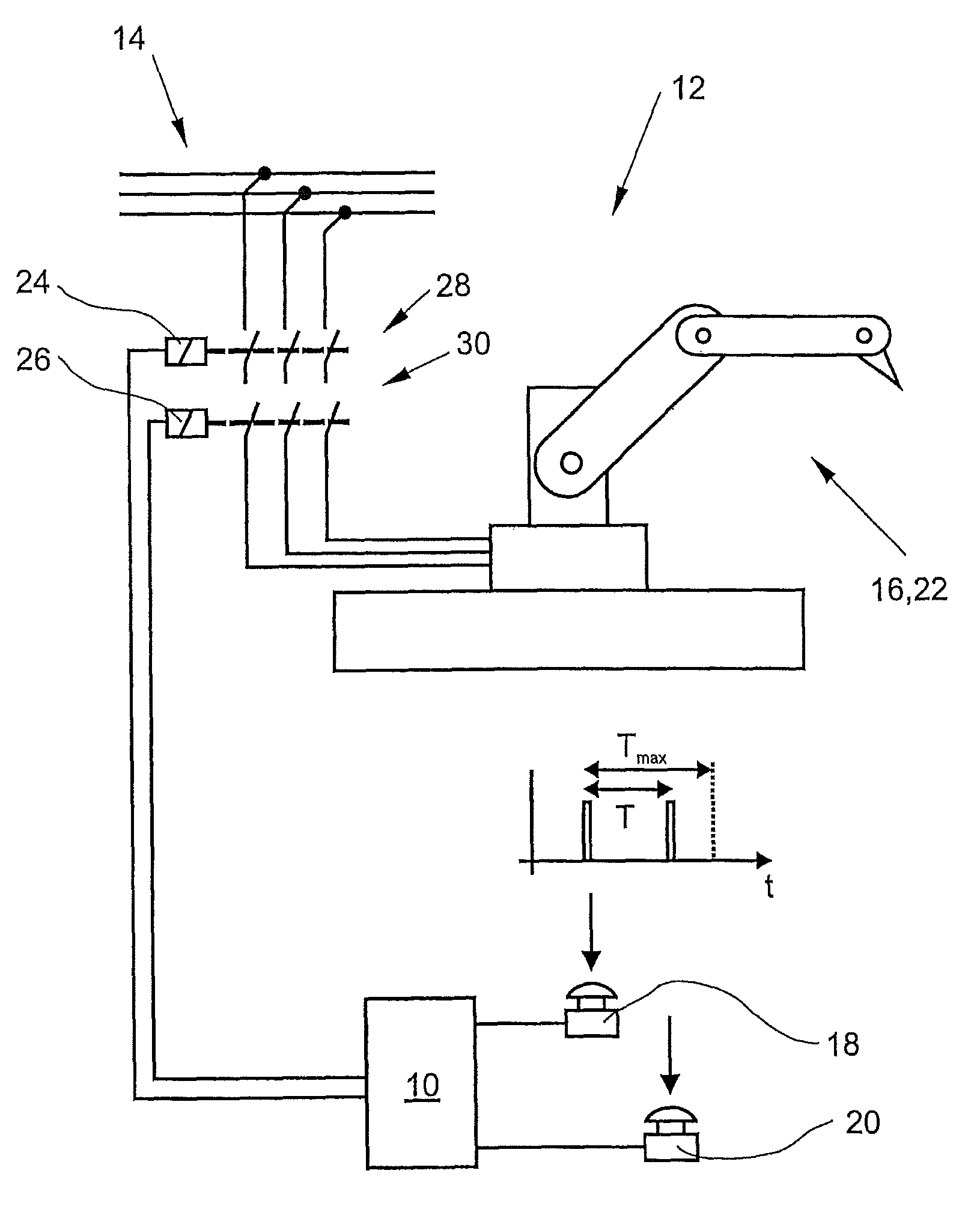
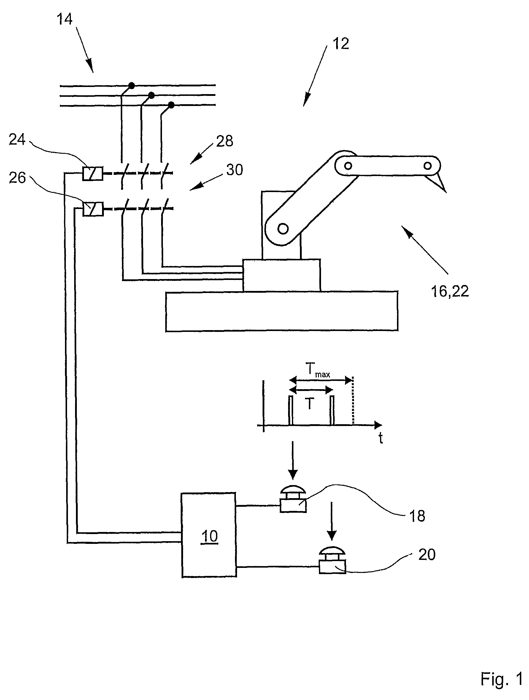
[0062]In FIG. 1, a construction with the novel safety switching apparatus 10 is denoted in its entirety by the reference numeral 12. The construction 12 in this case contains a power supply 14, a machine 16 and the safety switching apparatus 10, to which a first signaling device 18 and a second signaling device 20 are connected.

[0063]The machine 16 is a load 22, which can only be switched on for a working operation when the time span T between an actuation of the first signaling element 18 and an actuation of the second signaling element 20 is below a predetermined maximum duration Tmax.

[0064]In order to switch the machine 16 on, the safety switching apparatus 10 drives two contactors 24, 26, whose working contacts 28, 30 are arranged so as to be connected between the power supply 14 and the machine 16. The machine 16 can only carry out the working operation when both contactors 24, 26 close their working contacts 28, 30.

[0065]If a fault is identified prior to or during the actuatio...


PUM


Abstract

The invention relates to a safety switching apparatus and to a method for safely switching on and off an electrical load, in particular an automated installation. The apparatus comprises a first port for a first signaling element, a second port for a second signaling element, a first switching device coupled to a first switching activator, and a second switching device coupled to a second switching activator. A time monitoring apparatus activates the first and the second switching activators only if a time between an actuation of the signaling elements is smaller than a predetermined maximum duration. The activation of the switching activators in turn causes the switching devices to be switched-through and thus the load to be switched on. For the activation of the switching activators, a first and a second switching element, which are each arranged in series with the switching activators, need to switched-through. According to one aspect of the invention, at least a first microcontroller is provided for the time monitoring, which microcontroller is designed to detect actuations of the signaling elements and to activate the switching elements in the event of the maximum duration being undershot.

Description

CROSS-REFERENCES TO RELATED APPLICATIONS[0001]This application is a continuation of international patent application PCT / EP2007 / 000644, filed on Jan. 25, 2007 designating the United States, which international patent application has been published in German language and claims priority from German patent application DE 10 2006 007 264.2, filed on Feb. 10, 2006. The entire contents of these priority applications are incorporated herein by reference.BACKGROUND OF THE INVENTION[0002]The invention relates to a safety switching apparatus for safely switching an electrical load, in particular an automated installation, on and off.[0003]The invention further relates to a method for safely switching an electrical load, in particular an automated installation, on and off.[0004]A safety switching apparatus within the meaning of the present invention is any switching apparatus which at least meets category 3, preferably even category 4, of the European standard EN 954-1 or a comparable safety ...

Claims


Application Information

Patent Timeline
Patent Type & Authority Patents(United States)
IPC IPC(8): H02H11/00F16P3/20
CPCH01H47/005H01H2300/054
Inventor NITSCHE, THOMASRATEY, UDOZINSER, CHRISTOPH
Owner PILZ (COMPANY)
Why Eureka
Try Eureka