System and method for monitoring the condition of a drive train

a technology for driving trains and gearboxes, applied in the direction of fluid pressure measurement by mechanical elements, vibration measurement in solids, wind energy generation, etc., can solve the problems of failure or damage of gears or bearings, simple wear and tear of gears and bearings in a gearbox,

Active Publication Date: 2011-03-22
GENERAL ELECTRIC CO
View PDF20 Cites 27 Cited by
  • Summary
  • Abstract
  • Description
  • Claims
  • Application Information

AI Technical Summary

Problems solved by technology

The gears and bearings in a gearbox may have defects, or they may fail over time, or they may simply wear out.
For example, the loads and stresses that are imposed on the bearings and gears may exceed acceptable limits, leading to failure or damage to the gears or bearings.
Alternatively, the teeth may simply begin to wear down through prolonged usage.
However this method may not be practical because the resonance frequency is variable.

Method used


Image

  • System and method for monitoring the condition of a drive train
  • System and method for monitoring the condition of a drive train
  • System and method for monitoring the condition of a drive train

Examples


Embodiment Construction

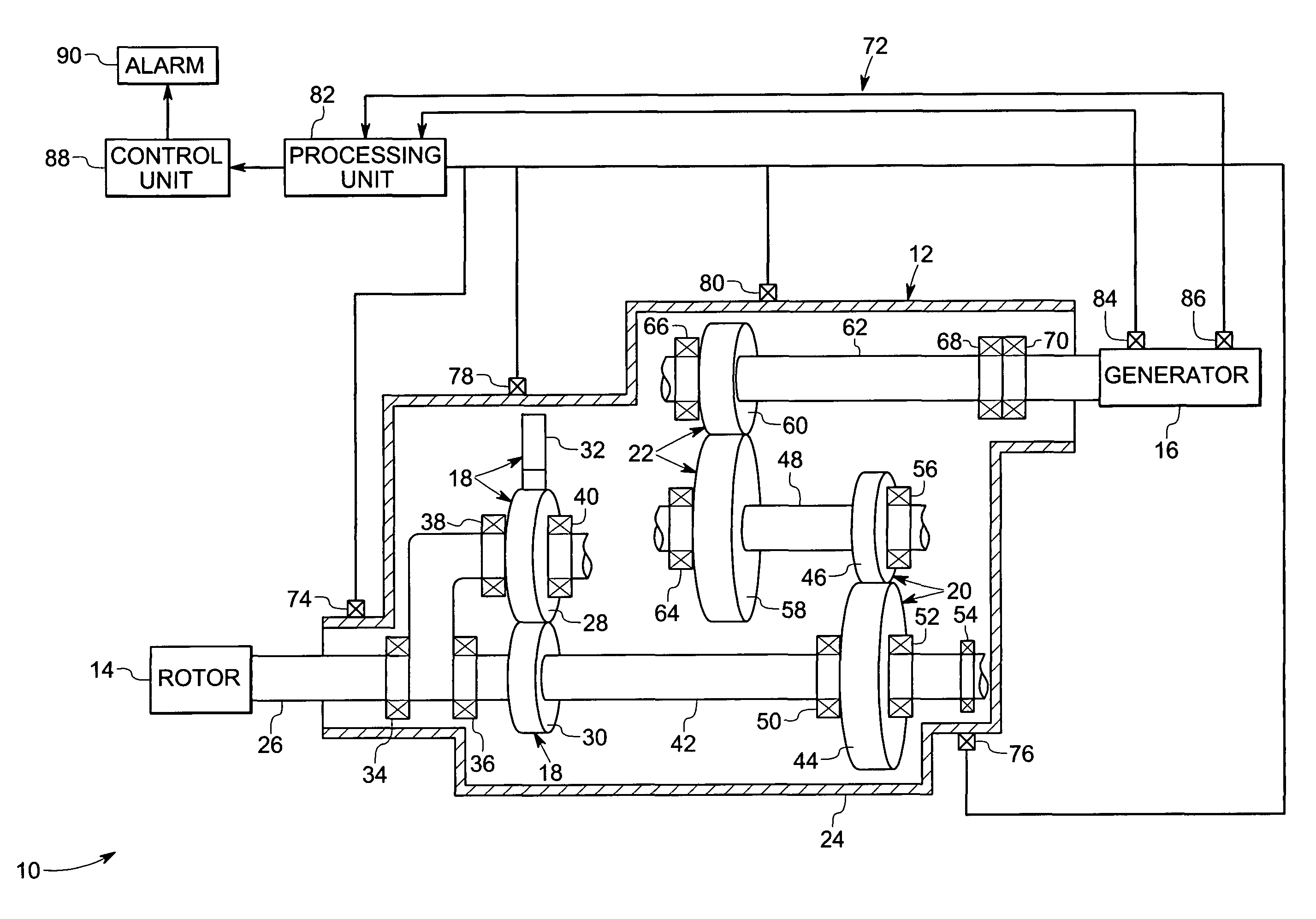
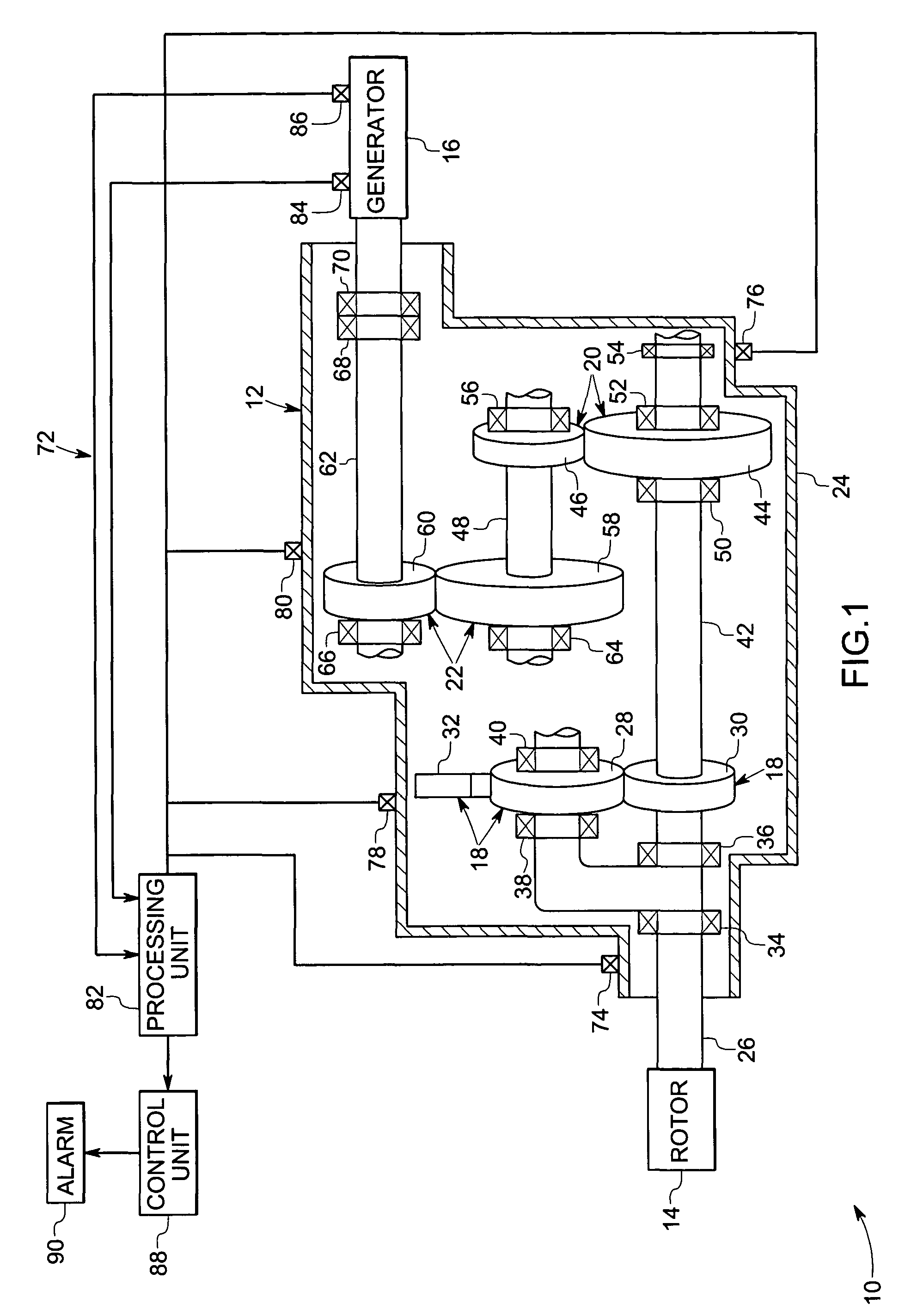
[0015]Referring generally to FIG. 1, a rotating electric machine is illustrated, and represented generally by reference numeral 10. In this embodiment, the rotating electric machine is a wind turbine. However the techniques described below are applicable to other power generation machines as well as various other applications. The wind turbine 10 may rotate at a speed of approximately 18 revolutions per minute. However, the speed may vary. In this embodiment, the wind turbine 10 has a gearbox 12 provided between a rotor 14 and a generator 16. The rotor 14 has a plurality of rotor blades (not shown). As the wind blows, the rotor 14 is rotated due to the force of the wind. The rotation of the rotor 14 is transmitted via the gearbox 12 to the rotor of the generator 16. The rotor 14 is designed to transfer wind energy into rotation efficiently. However, the rotor of the generator 16 is designed to operate at a much greater speed. The gearbox 12 is designed to increase the speed of rotat...


PUM

PropertyMeasurementUnit
frequencyaaaaaaaaaa
frequencyaaaaaaaaaa
frequencyaaaaaaaaaa

Abstract

A gearbox condition monitoring system includes at least one vibration sensor located on a gearbox casing. A processing unit is coupled to the vibration sensor and is configured to receive signals representative of the detected vibrations from the vibration sensor. The processing unit may be operable to process the signals representative of detected vibrations of gears and bearings and to compute at least one dynamic energy index or location of fault.

Description

BACKGROUND[0001]The invention relates generally to techniques for monitoring the condition of a drive train, and more specifically to a technique for monitoring the condition of gears and bearings within a gearbox of a drive train.[0002]A gear is a machine part that is designed to mesh with another similar machine part to transmit rotational motion. The most commonly used gears include planetary gears, spur gears, helical gears, bevel gears, worm gears, and rack and pinion gears. Gears mesh with each other in many different ways to transfer motion from one gear to another. In addition, gears can be used to increase or decrease the speed of rotation. For example, a smaller gear driven by a larger gear will have a greater speed of rotation than the larger gear. Conversely, a larger gear driven by a smaller gear will have a lower speed of rotation than the smaller gear. Gears may be housed in a gearbox. Gearboxes are used to transmit rotational motion in many different types of systems...

Claims


Application Information

Patent Timeline
Patent Type & Authority Patents(United States)
IPC IPC(8): G01L7/00G01B5/30F16H37/04F16H57/00F16H59/68F16H61/12G01D3/08G01M13/02G01M13/04
CPCF03D11/02F16H57/01G01M13/028G01M13/045F05B2260/80F16H37/041F16H2057/012Y02B10/30Y02E10/722F03D15/00F03D9/25F03D15/10F03D17/00F03D80/70Y02E10/72
Inventor LUO, HUAGENG
Owner GENERAL ELECTRIC CO
Why Eureka
Try Eureka