
Adaptor and method for converting standard tube fitting/port to push-to-connect tube fitting/port

a technology for adapters and tubes, applied in the direction of pipe joints, fluid pressure sealed joints, sleeves/socket joints, etc., can solve the problems of somewhat difficult annular seal installation or replacement of worn annular seals

Active Publication Date: 2011-03-29
PARKER INTANGIBLES LLC
View PDF135 Cites 37 Cited by
  • Summary
  • Abstract
  • Description
  • Claims
  • Application Information

AI Technical Summary

Benefits of technology

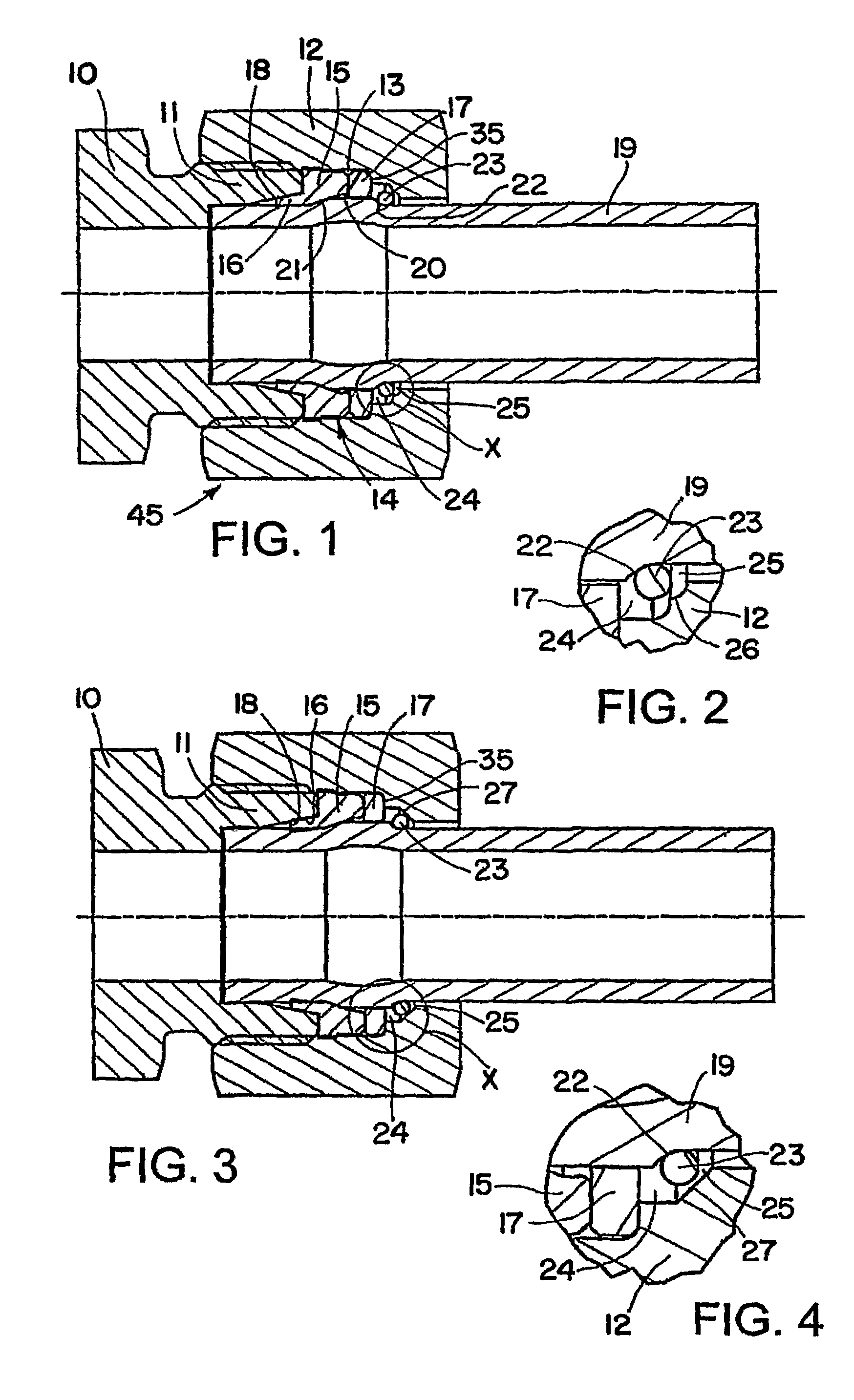
[0009]Accordingly, a standard 24° cone fitting body can be used without constructional change because the sealing of the tube is shifted into the region of the coupling nut, i.e. in the chamber of the coupling nut in which the lock ring also is arranged. The sealing ring provides at the same time a support surface for preventing axial shifting movement of the lock ring when the tube is push through the lock ring to cause lock ring to radially expand for sliding along the outer diameter of the tube. The internally threaded portion of the coupling nut is sized to allow for axial insertion of the sealing ring and lock ring into the interior chamber of the coupling nut, thereby eliminating any need to form lock ring groove in the radial wall of the coupling nut. Finally it is desirable that the locking surface be provided on the push-in tube deforming the wall of the tube.

Problems solved by technology

The position of the seal also makes it somewhat difficult to install the annular seal or replace a worn annular seal as may be needed during the life of the coupling.

Method used


Image

  • Adaptor and method for converting standard tube fitting/port to push-to-connect tube fitting/port
  • Adaptor and method for converting standard tube fitting/port to push-to-connect tube fitting/port
  • Adaptor and method for converting standard tube fitting/port to push-to-connect tube fitting/port

Examples


embodiment

FIG. 9 Embodiment

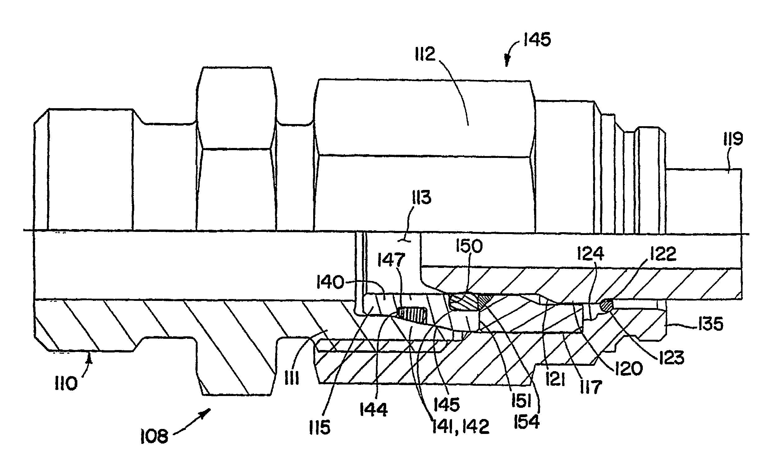
[0050]FIG. 9 shows another adaptor 145 according to the invention for converting a fitting body 110, particularly a standard 24° cone body, to a push-to-connect tube fitting assembly 108. The threaded fitting body 110 has a threaded connecting portion 111 provided with an appropriate thread onto which a coupling nut 112 is screwed to form a chamber 113 between a bottom wall 135 of the coupling nut 112 and a conical end of the threaded fitting body 110. Within this chamber 113 there is arranged a sealing ring 114 which includes a seal part 115 and a support ring 117 (which may also be referred to as a backup ring).

[0051]Unlike the embodiment shown in FIGS. 1 and 2, the seal part 115 includes a seal carrier 140 and a pair of annular seals, such as O-rings 141 and 142. The seal 141 is retained in an annular groove 144 formed in the outer surface of a conical portion 145 of the carrier. The conical portion 145 has the same cone angle as the interior surface 147 of the c...


PUM


Abstract

An adaptor (45) for converting to a push-to-connect tube fitting / port a standard tube fitting / port body (10, 110, 210, 310, 410, 510, 610) having a threaded portion (11) for threaded attachment of a nut / plug (12), comprises a coupling nut / plug (12, 112, 212, 312, 412, 512, 612) having an axially inner threaded end portion for threaded attachment to the threaded portion (11) of the fitting / port body (10); a tube sealing member (15, 115, 215, 315, 415, 515, 615) contained within the nut / plug (12) for sealing to a tube (19) having a locking surface (22) spaced from the end of the tube (19); and a retention device (23) retained in the nut / plug (12), which nut / plug (12) has at an axially outer end thereof a central opening through which the tube (19) can be inserted into the coupling nut / plug (12), whereby the locking surface (22) can be engaged by the retention device (23) to prevent axial withdrawal of the tube (19) from the coupling nut / plug (12) once inserted; wherein sealing and retention of the tube (19) is effected within the confines of the coupling nut / plug (12) and separate from and without requiring modification of the standard tube fitting / port body (10).

Description

[0001]This application is a national phase of International Application No. PCT / US2005 / 26271 filed Jul. 21, 2005 and published in the English language.[0002]The invention herein described relates generally to tube fittings and ports. More particularly, the invention relates to an adaptor and method converting a standard tube fitting / port to push-to-connect tube fitting / port into which a tube can be pushed to effect a secure and sealed connection with the standard tube fitting / port by means of the adaptor.BACKGROUND OF THE INVENTION[0003]Push-to-connect tube couplings heretofore have been provided to allow for quick connection and sealing of a tube to the coupling simply by inserting the tube into the coupling. One such push-to-connect tube coupling is described in U.S. Pat. No. 4,063,760. Here a coupling nut is screwed onto the threaded portion of a tubular body having a forward threaded end for connection to another device. A radially expandable lock ring is provided in a chamber i...

Claims


Application Information

Patent Timeline
Patent Type & Authority Patents(United States)
IPC IPC(8): F16L39/00
CPCF16L19/0231F16L37/088F16L37/0887
Inventor UDHOFER, ANDREASEHRKE, DIETERPATEL, HIRALALGIROD, KENNETH P.MOREIRAS, LUISWEIL, ANDREASYU, LE
Owner PARKER INTANGIBLES LLC
Learn More