
Apparatus, system, and method for creating an electrical connection to a tool

a technology of electrical connection and apparatus, applied in the field of electrical clips, can solve the problems of difficulty in similar difficulties may arise with any tool, and the difficulty of using the tool according to its designed function

Active Publication Date: 2011-03-29
CADWELL LAB
View PDF16 Cites 63 Cited by
  • Summary
  • Abstract
  • Description
  • Claims
  • Application Information

AI Technical Summary

Benefits of technology

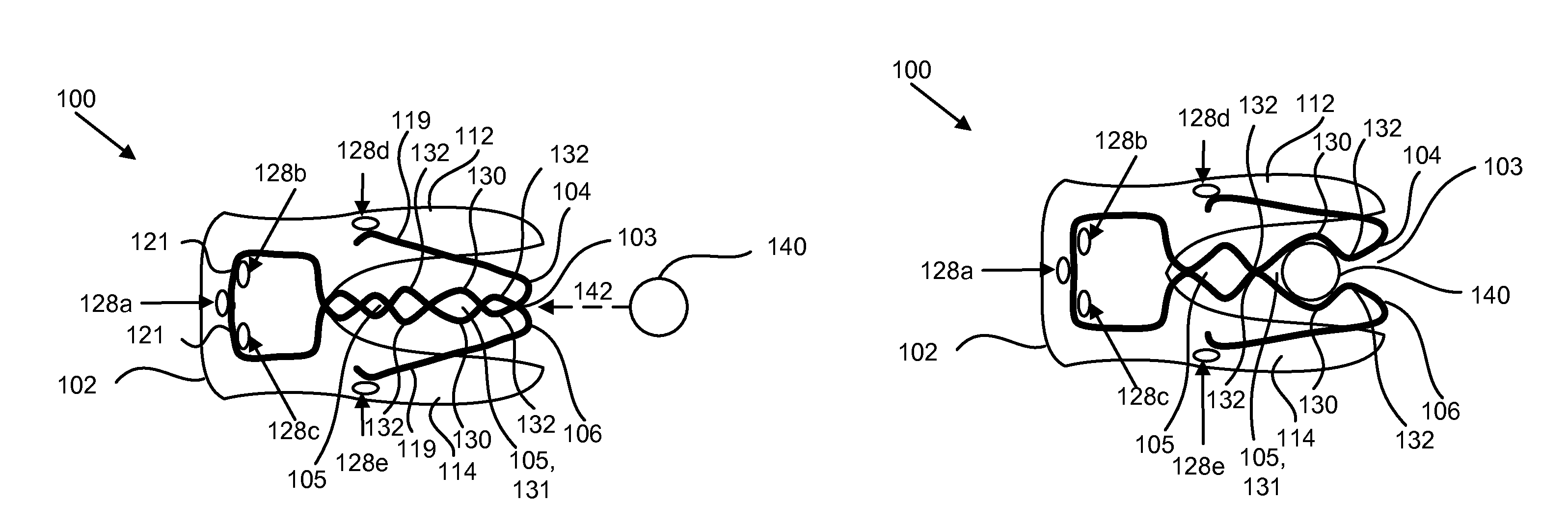
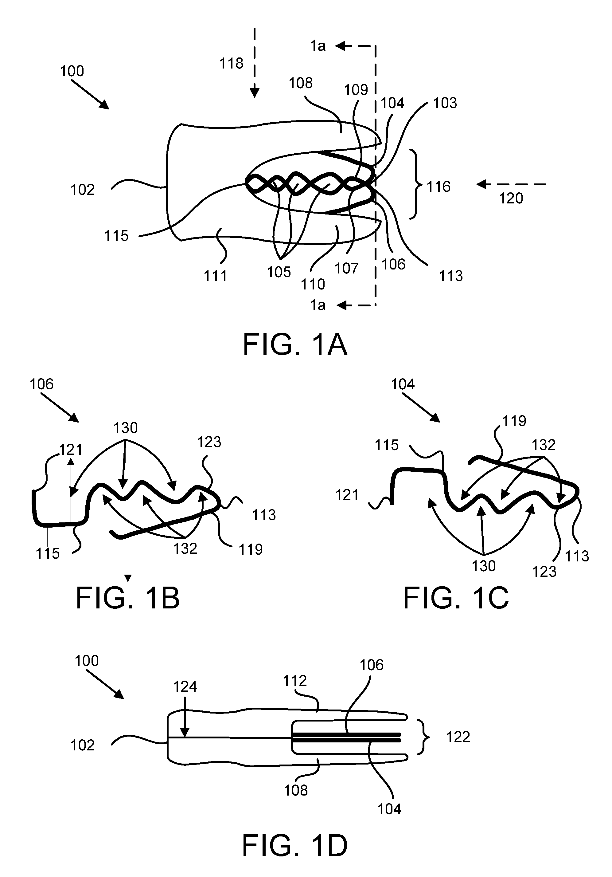
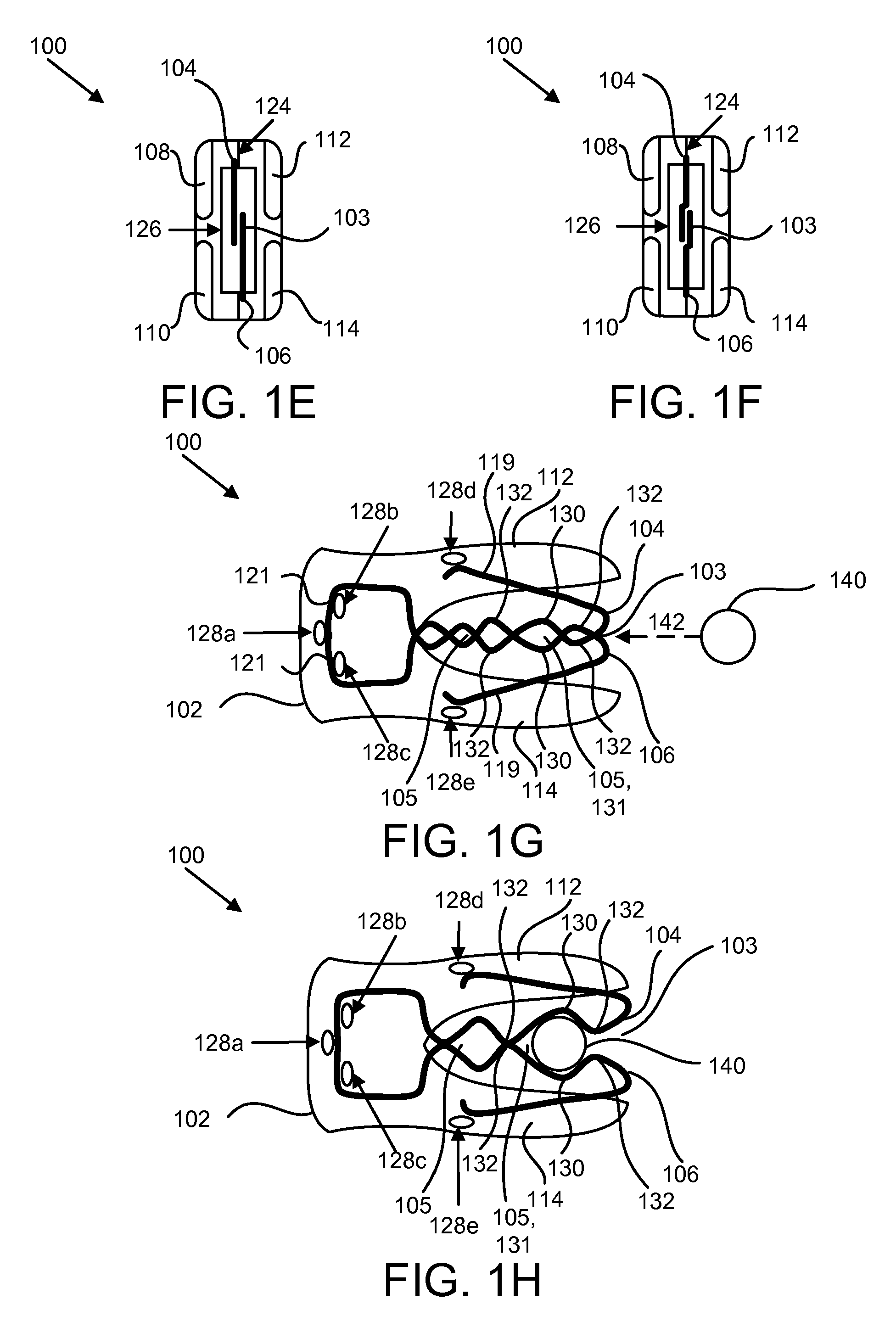
The present invention provides an apparatus, system, and method for creating an electrical connection with an electrically conductive element while maintaining an electrical connection when the tool is rotated. The apparatus includes a first contact element, a second contact element, and at least one stage formed in a scissor-like jay created by the first and second contact elements. The first and second contact elements are made of an electrically conductive material that conducts an electrical current between the elements. The apparatus also includes a housing that engages the first and second contact elements to bias the scissor-like jay in a closed position. The invention solves the problem of maintaining an electrical connection when the tool is rotated and provides a more efficient and effective solution for creating electrical connections.

Problems solved by technology

However, because surgical tools are often used to perform very delicate and accurate steps, the attached electrical clip and corresponding cord may make it difficult to use the tool according to its designed functions.
This can cause difficulties in using the tool when an electrical clip is attached because the cord may wrap around the tool.
Similar difficulties may arise with any tool that is designed to both deliver an electrical current and perform additional operations or functions which require the tool to be rotated or manipulated.

Method used


Image

  • Apparatus, system, and method for creating an electrical connection to a tool
  • Apparatus, system, and method for creating an electrical connection to a tool
  • Apparatus, system, and method for creating an electrical connection to a tool

Examples


Embodiment Construction

[0043]Reference throughout this specification to “one embodiment,”“an embodiment,” or similar language means that a particular feature, structure, or characteristic described in connection with the embodiment is included in at least one embodiment of the present invention. Thus, appearances of the phrases “in one embodiment,”“in an embodiment,” and similar language throughout this specification may, but do not necessarily, all refer to the same embodiment.

[0044]Furthermore, the described features, structures, or characteristics of the invention may be combined in any suitable manner in one or more embodiments. In the following description, numerous specific details are provided to provide a thorough understanding of embodiments of the invention. One skilled in the relevant art will recognize, however, that the invention may be practiced without one or more of the specific details, or with other methods, components, materials, and so forth. In other instances, well-known structures, ...


PUM


Abstract

An apparatus, system, and method are disclosed for creating an electrical connection with an electrically conductive element. The apparatus includes a first contact element having an engagement surface for engaging a first side of the electrically conductive element and a second contact element positioned opposite the first contact element includes an opposing engagement surface for engaging a second side of the electrically conductive element. The first contact element is slideable past the second contact element to form a scissor-like jaw. A valley formed in at least one of the engagement surface and the opposing engagement surface of the first and second contact elements creates a stage. At least one of the first and the second contact elements are made of an electrically conductive material that conducts an electrical current between the electrically conductive element and at least one of the first and second contact elements.

Description

FIELD OF THE INVENTION[0001]This invention relates to electrical clips that engage an electrically conductive element to create an electrical connection between the electrical clip and the electrically conductive element and more particularly relates to electrical clips that allow a conductive shaft of an electrically conductive element to rotate while maintaining an electrical connection to the electrically conductive element.BACKGROUNDDescription of the Related Art[0002]Electrical connectors of various types are used for various purposes. One such purpose is the application of an electrical current to a surgical tool. Often, an electrical clip is connected via an electrical cord to a power source. This allows a surgeon or other medical staff to determine if he or she is working to close to a nerve. However, because surgical tools are often used to perform very delicate and accurate steps, the attached electrical clip and corresponding cord may make it difficult to use the tool acc...

Claims


Application Information

Patent Timeline
Patent Type & Authority Patents(United States)
IPC IPC(8): H01R4/48
CPCA61B18/14H01R11/24A61B2018/00178H01R2201/12Y10S439/909
Inventor BOZICH, JOHN M.CADWELL, JOHN
Owner CADWELL LAB
Learn More