Method and apparatus for locating the source of radio frequency emissions

a radio frequency emission and source technology, applied in direction finders, radio wave direction/deviation determination systems, instruments, etc., can solve the problems of multi-path interference, difficult to locate electromagnetic radio frequency emission, and inability to produce accurate direction of arrival measurements of conventional radio direction finding equipmen

Inactive Publication Date: 2011-03-29
WISTERIUM DEV
View PDF10 Cites 20 Cited by
  • Summary
  • Abstract
  • Description
  • Claims
  • Application Information

AI Technical Summary

Problems solved by technology

Electro-magnetic radio frequency emissions can be difficult to locate, especially emissions found above 100 MHz.
This is due to the relatively short wavelength of emissions in these frequency bands, which are easily reflected by objects near the emitter or receiver causing multi-path interference.
Conventional radio direction finding equipment does not produce accurate direction of arrival measurements for reasonable antenna sizes under these conditions.
In addition, conventional radio direction finding equipment typically uses a complex antenna array, which requires careful calibration prior to use.
Thus, a heretofore unaddressed need exists in the industry to address the aforementioned deficiencies and inadequacies.

Method used


Image

  • Method and apparatus for locating the source of radio frequency emissions
  • Method and apparatus for locating the source of radio frequency emissions
  • Method and apparatus for locating the source of radio frequency emissions

Examples


Embodiment Construction

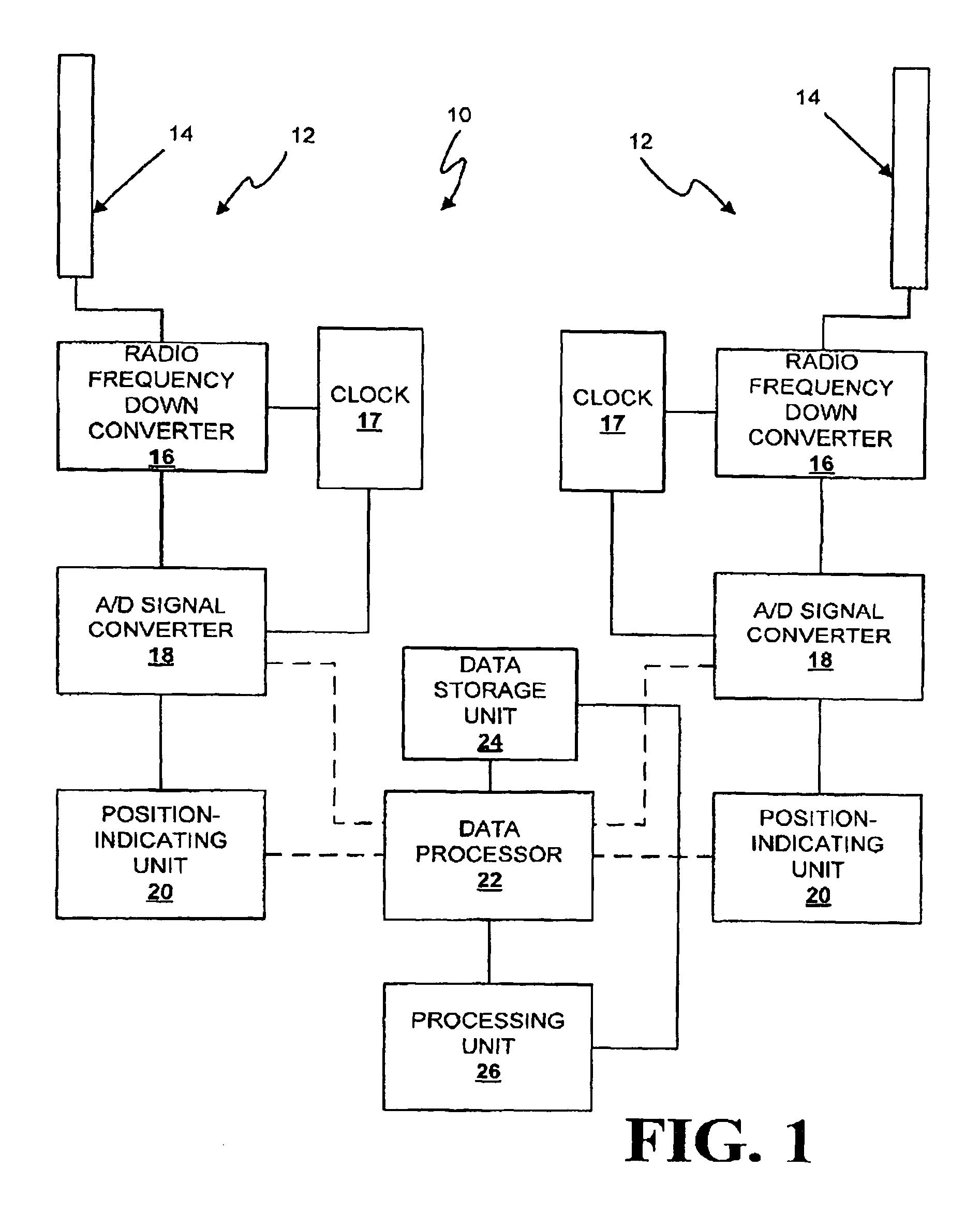
[0014]FIG. 1 is a block diagram of a radio frequency emission source locator 10, in accordance with a first exemplary embodiment of the invention. At least two receiver sets 12 are provided. Each receiver set 12 includes an antenna 14 capable of receiving radio frequency emissions, a radio frequency down converter 16, an analog / digital signal converter 18, and a position-indicating unit 20. A data processor 22 is in communication with the receiver sets 12, wherein the data processor 22 combines signals from the analog / digital signal converter 18 and the position-indicating unit 20 to produce tagged data. The tagged data includes sampled, down converted radio frequency data (The data are measurements of the antenna voltages translated in frequency and converted from analog voltages to a digital representation by the radio frequency down converter 16 and the analog / digital signal converter 18), from at least one signal received by each of the antennas 14, and position-indicating unit ...


PUM


Abstract

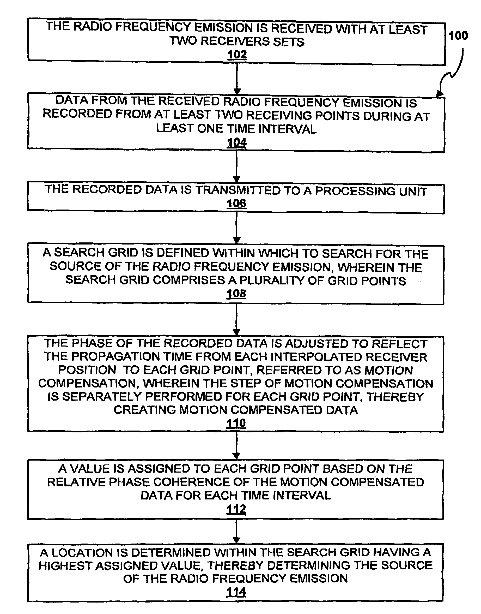
At least two receiver sets are provided. A data processor is in communication with the receiver sets, wherein the data processor tags position data and radio frequency emission data from the receiver sets. A data storage unit is in communication with the data processor and is at least capable of storing tagged data. A processing unit is capable of processing the tagged data. The processing unit defines a search grid within which to search for the source of the radio frequency emission. The processing unit motion compensates the tagged data separately for each point on the grid. The processing unit assigns a value to each grid point based on a phase coherence of the motion compensated data. The processing unit determines a location within the grid having a highest assigned value, thereby determining the source of the radio frequency emission.

Description

CROSS-REFERENCE TO RELATED APPLICATION[0001]This application claims the benefit of U.S. provisional patent application Ser. No. 60 / 621,765, filed Oct. 25, 2004, and entitled “Method and Apparatus for Locating the Source of Radio Frequency Emissions”, which is incorporated herein by reference in its entirety.FIELD OF THE INVENTION[0002]The present invention relates to methods and apparatus for processing electromagnetic radio frequency signals and, more particularly, to methods and apparatus for locating the source of electromagnetic radio frequency emissions.BACKGROUND OF THE INVENTION[0003]Electro-magnetic radio frequency emissions can be difficult to locate, especially emissions found above 100 MHz. This is due to the relatively short wavelength of emissions in these frequency bands, which are easily reflected by objects near the emitter or receiver causing multi-path interference. Conventional radio direction finding equipment does not produce accurate direction of arrival measur...

Claims


Application Information

Patent Timeline
Patent Type & Authority Patents(United States)
IPC IPC(8): G01S3/02G01S3/46
CPCG01S3/04G01S3/14
Inventor KIMBALL, STEVEN F.
Owner WISTERIUM DEV
Why Eureka
Try Eureka