Medical apparatus, treatment instrument for endoscope and endoscope apparatus

a technology for endoscopy and treatment instruments, applied in the field of medical devices, can solve the problems of poor turning force transmitting performance, difficult to stop the turning of the function portion in the desired direction, and twist generated in the turning force transmitting member

Active Publication Date: 2011-04-05
OLYMPUS CORP
View PDF21 Cites 27 Cited by
  • Summary
  • Abstract
  • Description
  • Claims
  • Application Information

AI Technical Summary

Problems solved by technology

When the function portion provided at a distal end of the turning force transmitting member is turned by turning a hand-side of the turning force transmitting member having a poor turning force transmitting performance, in other words, having a high flexibility, twist generated in the turning force transmitting member due to the turning of the hand-side thereof is accumulated.
That is, in the turning force transmitting member with poor turning force transmitting performance, the turning of the hand-side thereof is not directly transmitted to the distal end, so that it is difficult to stop the turning of the function portion in a desired direction.
Therefore, when adjusting the direction of the function portion by turning the turning force transmitting member having poor turning force transmitting performance, the operator seldom succeeds in adjusting the direction of the function portion in a desired direction by a first turning operation.
Note that a turning force transmitting member having flexibility and rich turning force transmitting performance is expensive, and this is one reason why the treatment instrument becomes expensive.

Method used


Image

  • Medical apparatus, treatment instrument for endoscope and endoscope apparatus
  • Medical apparatus, treatment instrument for endoscope and endoscope apparatus
  • Medical apparatus, treatment instrument for endoscope and endoscope apparatus

Examples


first embodiment

[0049]the present invention will be described referring to FIGS. 1 to 18.

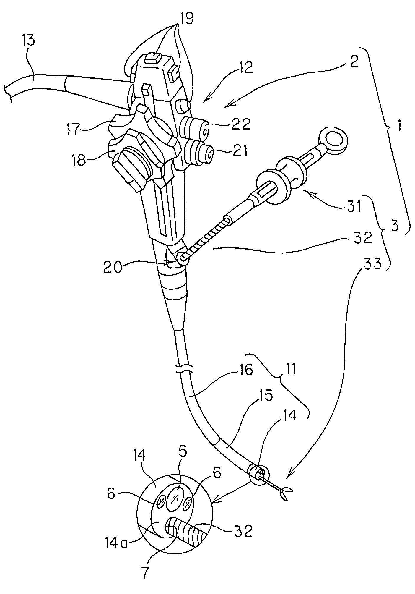
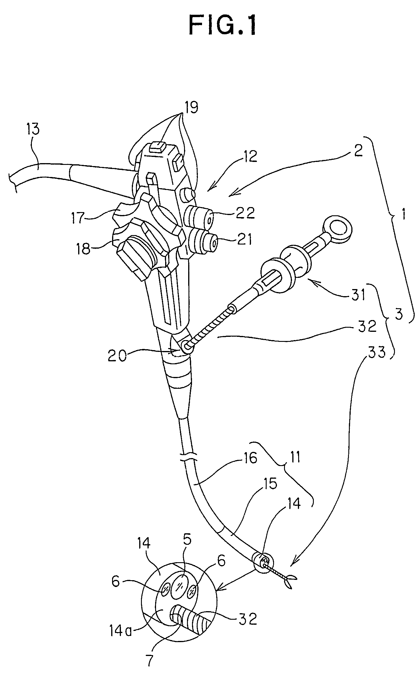
[0050]As shown in FIG. 1, an endoscope apparatus 1 includes an endoscope 2, and a biopsy forceps 3 as a medical device.

[0051]The endoscope 2 includes an insertion portion 11, an operation portion 12, and a universal cord 13. The insertion portion 11 consecutively includes in the following order from a distal end side thereof, a distal end constitution portion 14, a bending portion 15, and a flexible tube portion 16. The distal end constitution portion 14 includes a distal end surface 14a on which an observation window 5, an illumination window 6, a treatment instrument extracting port 7, and the like are provided. The operation portion 12 includes an up / down bending knob 17 for bending the bending portion 15, for example, in up and down directions, a right / left bending knob 18 for bending the bending portion 15, for example, in right and left directions, and various operation switches 19. The reference numeral ...

third embodiment

[0129]the present invention will be described referring to FIGS. 21 to 26.

[0130]In the third embodiment, the medical device is a papillotomy knife 80 as a kind of a high-frequency treatment instrument, which is provided with a turn restricting mechanism portion 50C. A direction of a dissection portion 33B which is a function portion of the papillotomy knife 80 is configured to be changed by 30 degrees in counterclockwise direction under a manual operation of an operation portion not shown.

[0131]The papillotomy knife 80 according to the present embodiment mainly includes a tubular flexible outer sheath 81 and an annular rigid turn restricting member 82 which constitute an elongated flexible insertion portion extended from the operation portion not shown; a tubular flexible inner sheath 83 as a turning force transmitting member which is inserted in the outer sheath 81, a conductive wire 84 inserted in the inner sheath 83, and a generally annular stopper member 85 disposed at a predete...

fourth embodiment

[0153]Description will be made on the present invention referring to FIGS. 27 to 29.

[0154]In the fourth embodiment, the medical device is the endoscope apparatus 90 provided with a turn restricting mechanism portion 50D as shown in FIGS. 27, 28. The endoscope apparatus 90 includes an endoscope 91 as an insertion portion, and a biopsy forceps 95 provided with a treatment portion 96 which is a function portion as well as a treatment instrument for endoscope and a coil sheath 97 which is a treatment instrument insertion portion as well as a turning force transmitting member. In the present embodiment, a direction of the treatment portion 96 of the biopsy forceps 95 can be changed by 90 degrees, for example, by turning operation of a sheath hand side 97a extending from a treatment instrument introducing port 94.

[0155]As shown in FIG. 27, the endoscope 91 includes an insertion portion 92, an operation portion 93, and the like. The insertion portion 92 includes in the following order from...


PUM


Abstract

A biopsy forceps as one of treatment instruments for endoscope includes: a tubular coil sheath introduced into a body cavity through a treatment instrument channel included in an endoscope insertion portion; a treatment portion disposed closer to a distal end side than a distal end surface of the coil sheath; an operation wire for transmitting a turning force to turn the treatment portion in a circumferential direction, the operation wire being inserted in the coil sheath in a forwardly / backwardly movable manner and turned in the circumferential direction; and a turn restricting mechanism portion for restricting a turn position of the treatment portion turned by the turning force transmitted by the operation wire with respect to the coil sheath at a first turn-restricting position or at a second turn-restricting position.

Description

BACKGROUND OF THE INVENTION[0001]1. Field of the Invention[0002]The present invention relates to a medical device capable of turning a direction of a function portion provided at a distal end of an insertion portion by a predetermined angle with respect to the insertion portion.[0003]2. Description of Related Art[0004]In recent years, an endoscope is widely used in the medical field. An endoscope includes an elongated insertion portion and an operation portion provided at a proximal end of the insertion portion. Generally, the elongated insertion portion has a distal end to which a bendable bending portion is provided. The operation portion is provided with, for example, a knob for operating and bending the bending portion, various switches for functioning various operations of the endoscope, a treatment instrument introducing port for inserting a treatment instrument for endoscope (hereinafter referred to as a treatment instrument) into a treatment instrument channel.[0005]An endos...

Claims


Application Information

Patent Timeline
Patent Type & Authority Patents(United States)
IPC IPC(8): A61B1/00A61B1/04
CPCA61B10/04A61B2017/2929A61B2017/2927A61B10/06
Inventor OKADA, TSUTOMUONUKI, YOSHIOICHIKAWA, HIROAKIMURAKAMI, KAZUSHIHONDA, KAZUKIKURA, YASUHITOKOMIYA, TAKAAKI
Owner OLYMPUS CORP
Why Eureka
Try Eureka