Cardiac stem cells

A technique of biopsy forceps and clamps, applied in the field of biopsy forceps

Inactive Publication Date: 2007-12-12
THE JOHN HOPKINS UNIV SCHOOL OF MEDICINE
View PDF0 Cites 15 Cited by
  • Summary
  • Abstract
  • Description
  • Claims
  • Application Information

AI Technical Summary

Problems solved by technology

Two handles attached to the proximal end of the catheter are used ...

Method used


Image

  • Cardiac stem cells
  • Cardiac stem cells
  • Cardiac stem cells

Examples


Embodiment Construction

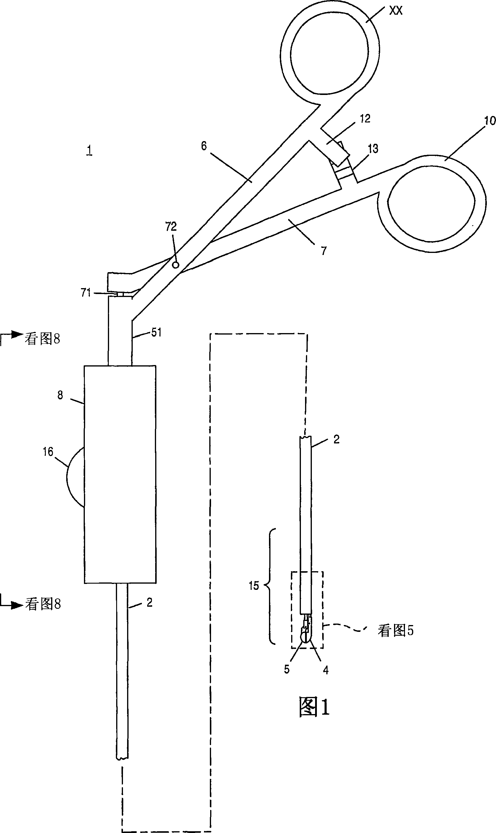
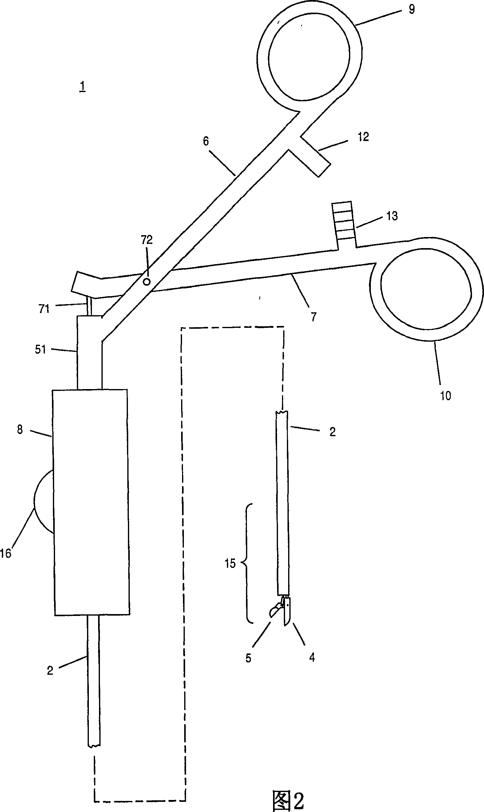
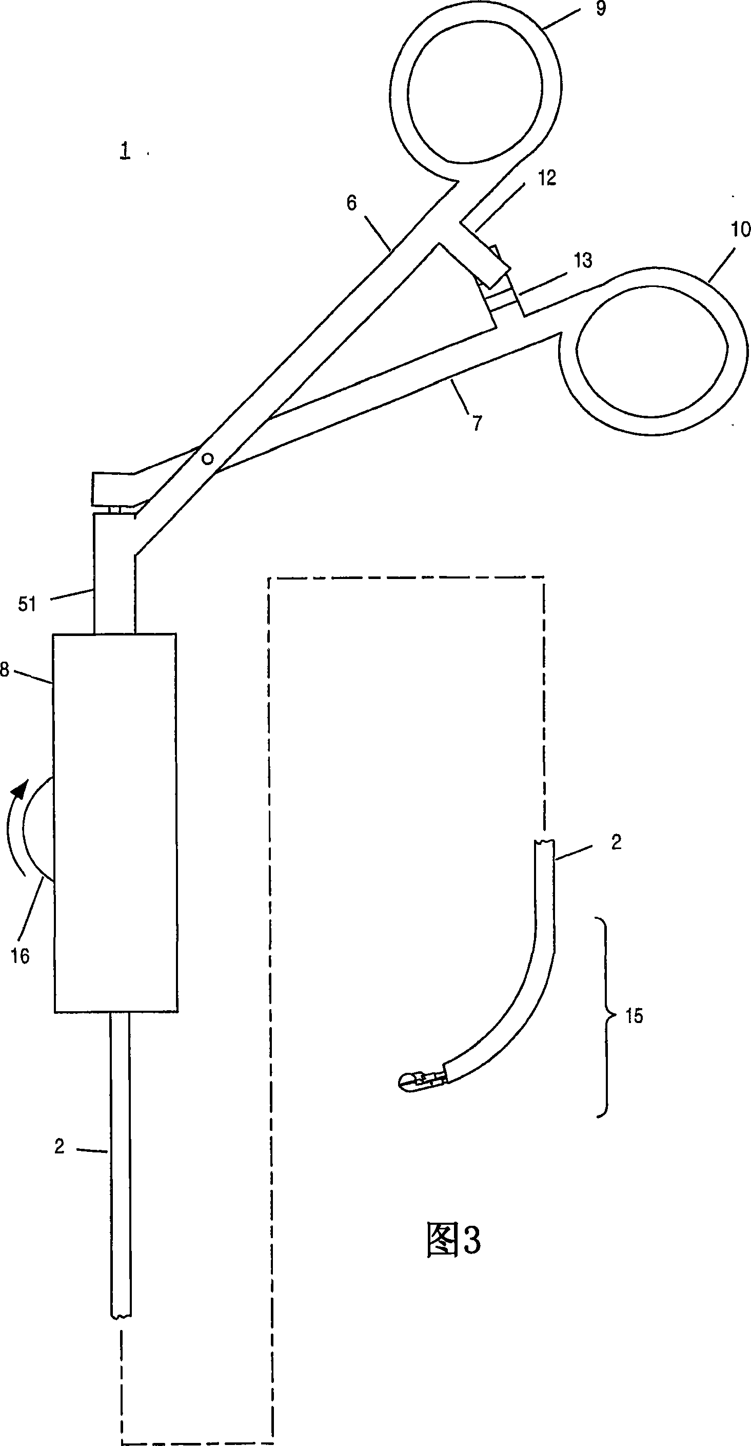
[0019] [18] Known biopsy forceps have several disadvantages. For example, existing biopsy forceps are relatively stiff. Typically, the catheter of the bioptome has limited flexibility, similar to the flexibility of a wire coat hanger. Limited flexibility sometimes prevents the bioptome catheter from reaching certain areas in the body. For example, certain areas that are only accessible via blood vessels and / or other passages that contain relatively large angle turns. Conventional bioptome catheters that cannot bend at these angles cannot reach the desired area without damaging the patient.

[0020] [19] In addition to being relatively rigid, the unmaneuverability of existing biopsy forceps limits the area from which tissue samples can be obtained. Specifically, physicians using existing bioptome forceps cannot alter the shape of the distal end of the catheter once the catheter is in the patient. Instead, catheter tips tend to follow the shape of the body lumen in which the...


PUM


Abstract

A biopsy forceps (1) comprises a flexible pipe (2) which can be remotely controlled. Two handles (6 and 7) which are connected to the near end of the pipe are used for operating a pair of clamps (4 and 5) that are connected to the far end of the pipe. An independent control handle (8) comprises a rotatable knob (16). The knob rotates in the reverse direction to facilitate the bending of the pipe in the second direction. A control knob can be connected to the far end of the pipe through the operating lines (42 and 43) that moves in the cavities (44 and 45) of the pipe in company with the rotation of the knob. The clamps (or other control component) at the far end of the pipe are replaceable (80A and 80B).

Description

[0001] Cross References to Related Applications [0002] [01] This application claims priority to Provisional US Patent Application No. 60 / 625,695, "Cardiac Stem Cells," filed November 8, 2004. Said patent application is hereby incorporated by reference in its entirety. Background of the invention [0003] 【02】Biopsy forceps are medical devices used to remove tissue samples from internal areas of an animal's body. Known bioptomes include a catheter with a pair of jaws at the distal end. The clamps generally have sharp edges that cut into tissue and a lumen that retains the tissue section when the clamps are closed. A pair of handles on the proximal end of the catheter are used to open and close the clamps. In use, the distal end of the catheter is typically inserted into a blood vessel of the patient (or animal) from which the desired tissue sample is taken. The clamps are then advanced to the area of ​​the body where a tissue sample is to be taken. Using the handle on th...

Claims


Application Information

Patent Timeline
IPC IPC(8): A61B10/00A61K35/12C12N5/077
CPCC12N2501/998C12N2501/115C12N2501/11C12N2500/44C12N2501/175A61K35/12C12N2533/52C12N5/0657C12N2533/32A61P9/00A61P9/02A61P9/04A61P13/12A61P43/00
Inventor E·马伯恩
Owner THE JOHN HOPKINS UNIV SCHOOL OF MEDICINE
Why Eureka
Try Eureka