Multi-purpose biopsy forceps

a biopsy forcep and multi-purpose technology, applied in the field of biopsy forceps, can solve the problems of large number of false negatives, random or blind biopsy procedure, and inability to be used in different patients (or in certain instances in different organs) to prevent cross-contamination

Active Publication Date: 2010-07-01
MAUNA KEA TECHNOLOGIES
View PDF27 Cites 19 Cited by
  • Summary
  • Abstract
  • Description
  • Claims
  • Application Information

AI Technical Summary

Problems solved by technology

Conventionally, forceps may be used successively in an organ or in a single patient, but they may not be used in different patients (or, in certain instances, in different organs) to prevent cross-contamination.
However, a drawback to the “gold standard” is that at very early stages of a pathology the biopsy procedure may be conducted randomly or blindly.
Such a practice may unfortunately lead to a large number of false negat

Method used


Image

  • Multi-purpose biopsy forceps
  • Multi-purpose biopsy forceps
  • Multi-purpose biopsy forceps

Examples


first embodiment

[0052]A first exemplary embodiment of the present disclosure is shown in FIGS. 8-14. In this first embodiment a biopsy unit may comprise a removable forceps and an optical probe. The forceps may comprise a pair of jaws that may be clipped onto an optical probe immediately before insertion into an accessory channel of an endoscope. The probe may be equipped with a mechanism to open and close the jaws through manipulation of a handle. After use, the jaws may be unclipped and separated from the optical probe. The jaws may then either be thrown away or disinfected separately (i.e., in a different or more rigorous process or machine).

[0053]Referring to FIG. 8, the forceps assembly 1 may be constructed from a single tubular structure. The proximal end of this structure may be left intact while the distal end may be split along its length into two halves which form jaws 1a. The intermediate portion, between the intact portion and the split portion, may be hollowed so that it may be relativ...

third embodiment

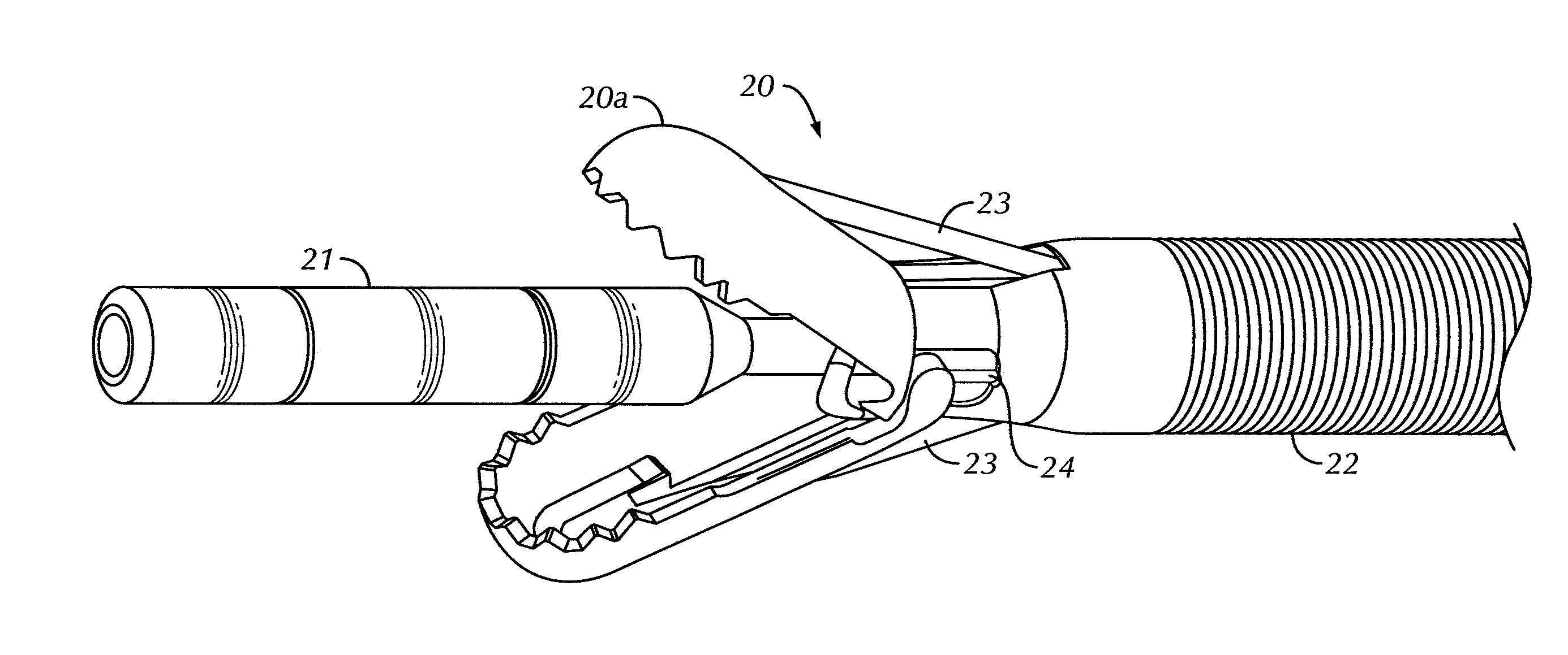
[0065]A third exemplary embodiment is shown in FIGS. 17-24. The biopsy unit, in accordance with this third embodiment, is shown in FIG. 17A, and a close-up view of the distal end of the unit is shown in FIG. 17B. Forceps 31, comprising jaws 31a, may be disposed at a distal end of the unit and may form an insertion cartridge 30 (see FIG. 18). Insertion cartridge 30 may be disposed within, and attached to a sleeve 34. Sleeve 34 may be attached to a distal end of a sheath 38. An endoscopic tool, such as an optical probe 32, may be disposed within the interiors of insertion cartridge 30, sleeve 34, and sheath 38. Jaws 31a may be operated by manipulation of a handle 50, employing a main part 51 and a sliding part 52, similar to that discussed above.

[0066]FIG. 18 shows the structure of insertion cartridge 30. Insertion cartridge 30 may comprise forceps 31, with jaws 31a, a locking portion 40, and a spring portion 41. As shown, insertion cartridge 30 may be a single, unitary design which m...


PUM


Abstract

A method to perform an endoscopic biopsy includes deploying a mechanical forceps through an accessory channel of an endoscope assembly, deploying an optical probe through the accessory channel to an area of investigation, optically evaluating tissue at the area of investigation, actuating the mechanical forceps to grasp a sample of the tissue, and retrieving the mechanical forceps and the optical probe through the accessory channel of the endoscope assembly. A biopsy apparatus includes a delivery conduit, an optical probe configured to investigate the tissue upon a distal end of an optical conduit extending through the delivery conduit, and a forceps assembly slidably engaged over the optical conduit, the forceps assembly comprising jaws configured to operate between a closed position and at least one open position, wherein the jaws of the forceps are urged into the closed position as the forceps are retracted within the delivery conduit.

Description

CROSS-REFERENCE TO RELATED APPLICATIONS[0001]The present application claims priority to U.S. Provisional Patent Application Ser. No. 61 / 141,995, filed on Dec. 31, 2008, hereby incorporated by reference in its entirety.BACKGROUND OF THE DISCLOSURE[0002]1. Field of the Disclosure[0003]The present disclosure relates to biopsy forceps compatible with endoscopic tools. More particularly, the present disclosure relates to biopsy forceps compatible with optical biopsy tools such that samples of the as-optically biopsied tissue may be retrieved for further analysis.[0004]2. Description of the Related Art[0005]A biopsy is a medical test involving the removal of cells or tissues for examination, referred to throughout as a mechanical biopsy. After extraction from a patient, the tissue is generally examined under a microscope by a pathologist, and may also be analyzed chemically. When an entire lump or suspicious area is removed, the procedure is called an excisional biopsy. When only a portio...

Claims


Application Information

Patent Timeline
IPC IPC(8): A61B10/04A61B10/06
CPCA61B1/018A61B10/04A61B10/06
Inventor LACOMBE, FRANCOISHUGHETT, DAVIDTIHANSKY, CHRISGENET, MAGALIE
Owner MAUNA KEA TECHNOLOGIES
Why Eureka
Try Eureka